SE201 · Annotated SlidesChapter 5.2 — System Modeling with UML
Chapter 5.2 · Annotated slides

System Modeling with UML

Context, interaction, structural and behavioral models, then UML in detail: use-case diagrams with include/extend/generalization, sequence diagrams and messages, class diagrams with association, aggregation, composition, generalization and multiplicity, activity diagrams with swimlanes, and state machine diagrams.
Slide text Study notes Highlight: key words Tips, tricks & traps Seen again elsewhere How it can come up
Slide 1: Slide 1
Exam weight Low

    Topics covered

    ◇

    Context models

    ◇

    Interaction models

    ◇

    Structural models

    ◇

    Behavioral models

    30/10/2014

    Chapter 5 System Modeling

    Topics covered
    2
    Exam weight Low

      System modeling

      ◇

      System modeling is the process of developing abstract models of a system, with each model presenting a different view or perspective of that system.

      ◇

      System modeling involves most of the time a graphical notation, the most widely used one being the Unified Modeling Language (UML).

      ◇

      System modelling helps the analyst understand the functionality of the system and models are used to better communicate with customers.

      30/10/2014

      Chapter 5 System Modeling

      System modeling
      3
      Exam weight Low

        Existing and planned system models

        ◇ Models of the existing system are used during requirements

        engineering. They help clarify what the existing system does and can be used as a basis for discussing its strengths and weaknesses. These then lead to requirements for the new system.

        ◇ Models of the new system are used during requirements

        engineering to help explain the proposed requirements to other system stakeholders. Engineers use these models to discuss design proposals and to document the system for implementation.

        ◇ In a model-driven engineering process, it is possible to generate

        a complete or partial system implementation from the system model.

        30/10/2014

        Chapter 5 System Modeling

        Existing and planned system models
        4
        Exam weight Low
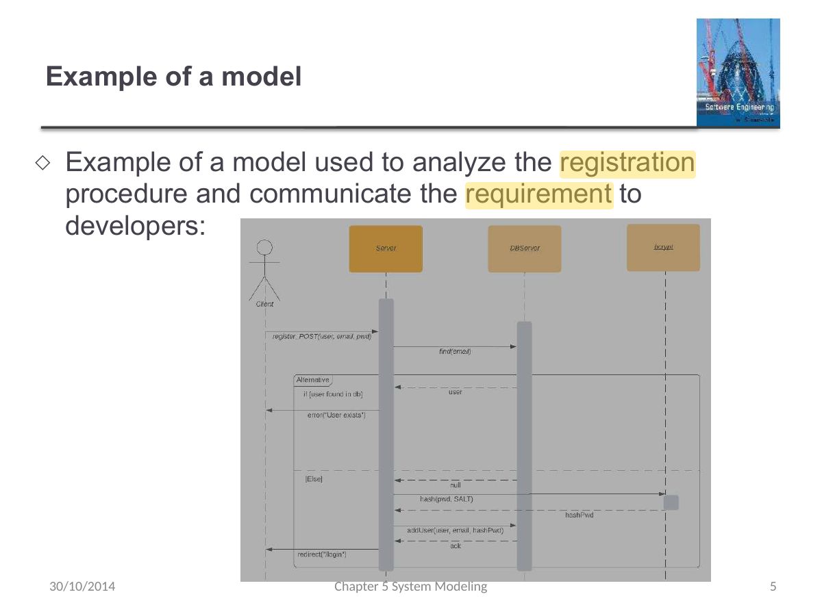
          Slide 5: Example of a model
          Exam weight Low

            Different Uses of graphical models

            ◇

            As a means of facilitating discussion about an existing or proposed system

            • Incomplete and incorrect models are OK as their role is to support discussion.

            ◇

            As a way of documenting an existing system

            • Models should be an accurate representation of the system but need not be complete.

            ◇

            As a detailed system description that can be used to generate a system implementation

            • Models have to be both correct and complete.

            30/10/2014

            Chapter 5 System Modeling

            Different Uses of graphical models
            6
            Exam weight Low

              System perspectives

              ◇

              An external perspective, where you model the context or environment of the system.

              ◇

              An interaction perspective, where you model the interactions between a system and its environment, or between the components of a system.

              ◇

              A structural perspective, where you model the organization of a system or the structure of the data that is processed by the system.

              ◇

              A behavioral perspective, where you model the dynamic behavior of the system and how it responds to events.

              30/10/2014

              Chapter 5 System Modeling

              System perspectives
              7
              Exam weight Low
              1. Perspectives: external (context), interaction, structural, behavioral.

              UML diagram types

              ◇

              Activity diagrams, which show the activities involved in a process or in data processing.

              ◇

              Use case diagrams, which show the interactions between a system and its environment.

              ◇

              Sequence diagrams, which show interactions between actors and the system and between system components.

              ◇

              Class diagrams, which show the object classes in the system and the associations between these classes.

              ◇

              State diagrams, which show how the system reacts to internal and external events.

              30/10/2014

              Chapter 5 System Modeling

              UML diagram types
              8
              Exam weight Low
              1. Key UML diagrams: activity, use case, sequence, class, state.

              Context models

              30/10/2014

              Chapter 5 System Modeling

              Slide 9
              9
              Exam weight Low

                Context models

                ◇

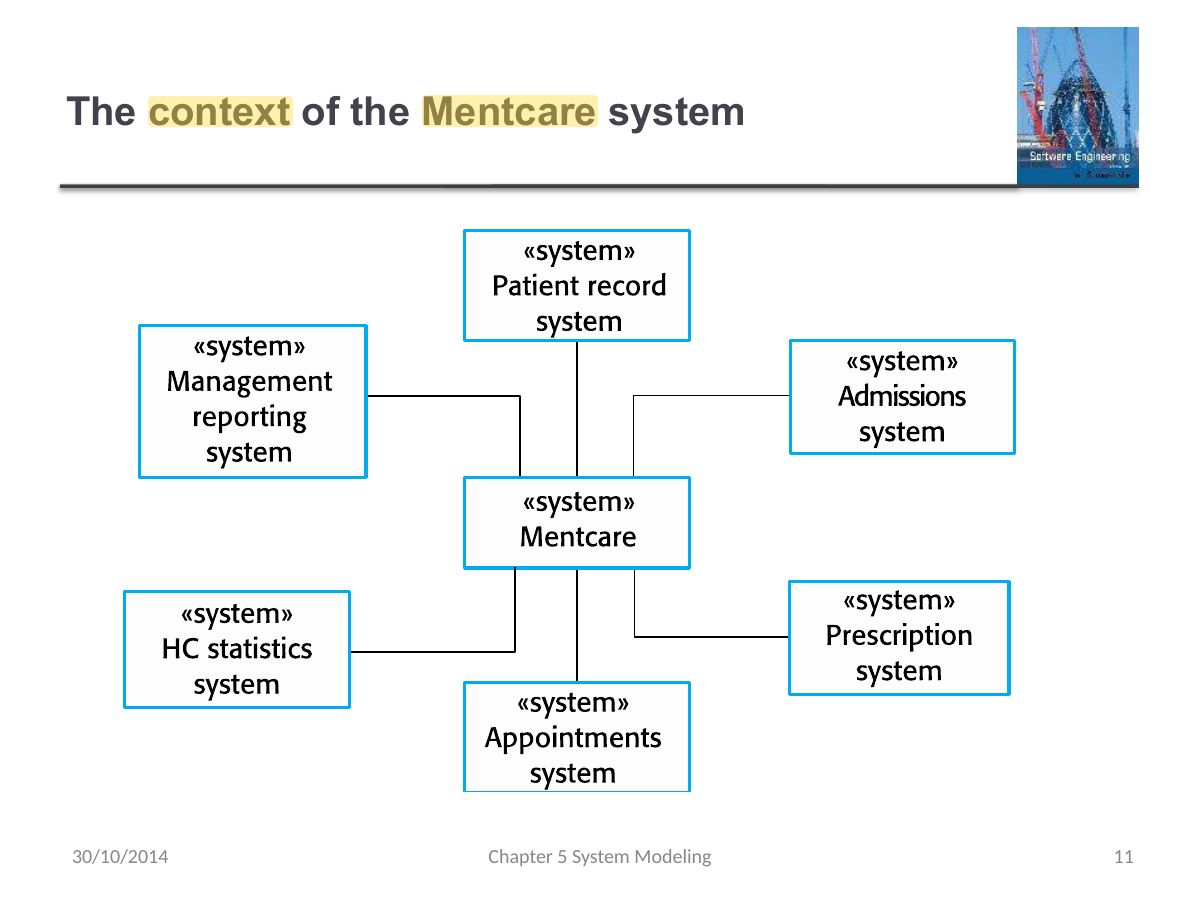
                Context models are used to illustrate the operational context of a system - they show what lies outside the system boundaries.

                ◇

                Architectural models show the system and its relationship with other systems.

                30/10/2014

                Chapter 5 System Modeling

                Context models
                10
                Exam weight Low
                1. Context model: shows the system boundary and the other systems around it.
                Slide 11: The context of the Mentcare system
                Exam weight Low

                  Process perspective

                  ◇

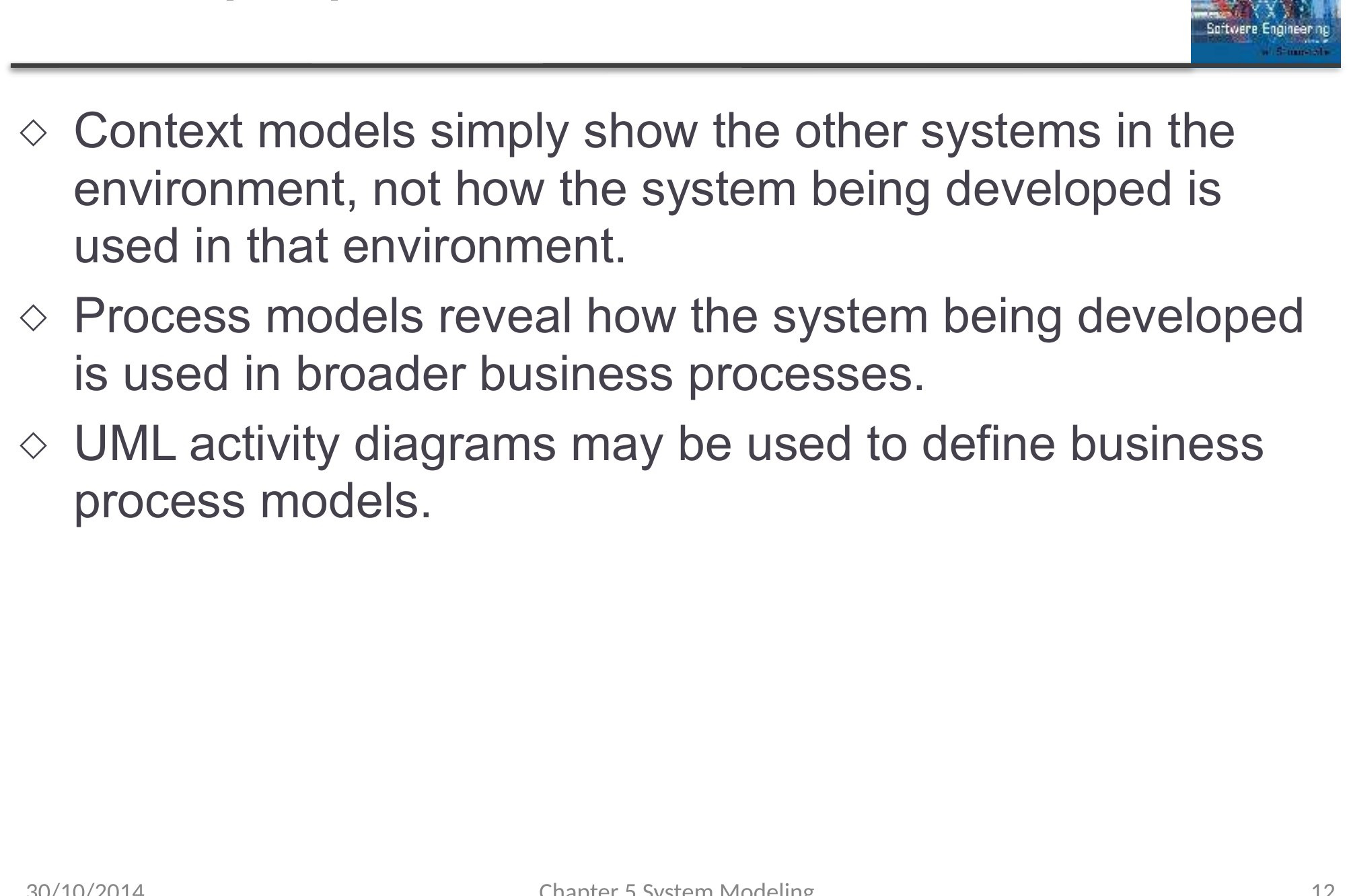
                  Context models simply show the other systems in the environment, not how the system being developed is used in that environment.

                  ◇

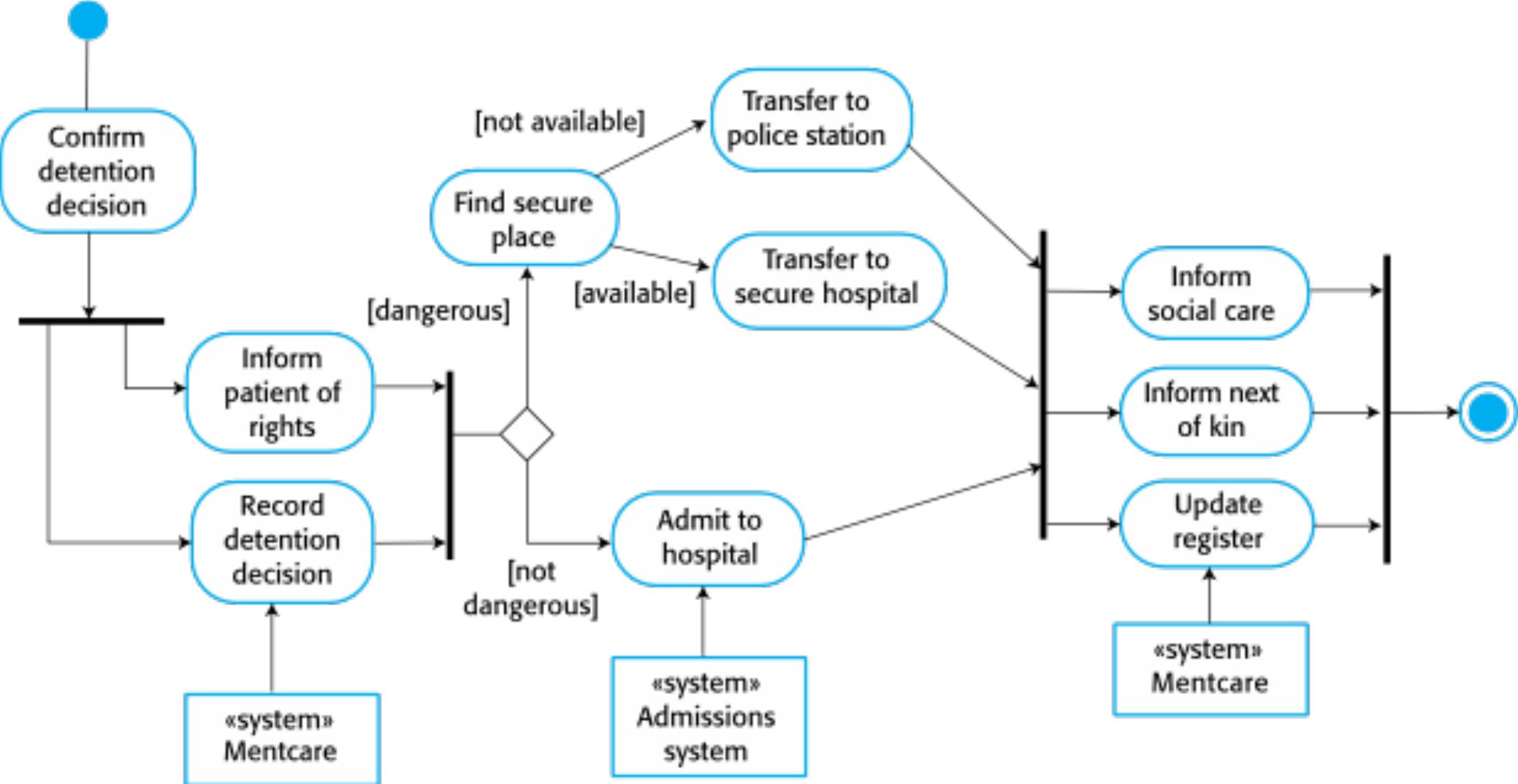
                  Process models reveal how the system being developed is used in broader business processes.

                  ◇

                  UML activity diagrams may be used to define business process models.

                  30/10/2014

                  Chapter 5 System Modeling

                  Process perspective
                  12
                  Exam weight Low

                    Process model of involuntary detention

                    30/10/2014

                    Chapter 5 System Modeling

                    Process model of involuntary detention
                    13
                    Exam weight Low

                      Interaction models

                      30/10/2014

                      Chapter 5 System Modeling

                      Slide 14
                      14
                      Exam weight Low

                        Interaction models

                        ◇

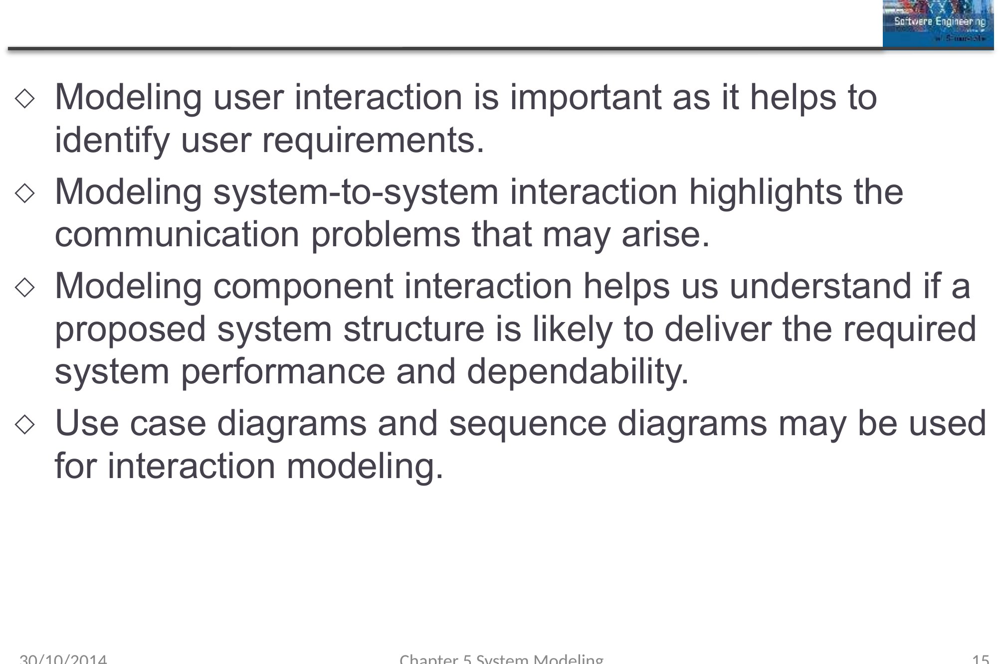
                        Modeling user interaction is important as it helps to identify user requirements.

                        ◇

                        Modeling system-to-system interaction highlights the communication problems that may arise.

                        ◇

                        Modeling component interaction helps us understand if a proposed system structure is likely to deliver the required system performance and dependability.

                        ◇

                        Use case diagrams and sequence diagrams may be used for interaction modeling.

                        30/10/2014

                        Chapter 5 System Modeling

                        Interaction models
                        15
                        Exam weight Low

                          Use case modeling

                          ◇

                          Use cases were developed originally to support requirements elicitation.

                          ◇

                          Each use case represents a discrete task that involves external interaction with a system.

                          ◇

                          Actors in a use case may be people or other systems.

                          ◇

                          Represented diagramatically to provide an overview of the use case and in a more detailed textual form.

                          ◇

                          Use case models and sequence diagrams present interactions at different levels of detail and so may be used together.

                          30/10/2014

                          Chapter 5 System Modeling

                          Use case modeling
                          16
                          Exam weight Low
                          1. Use case: a task an actor performs with the system; stick-figure actors and ovals.
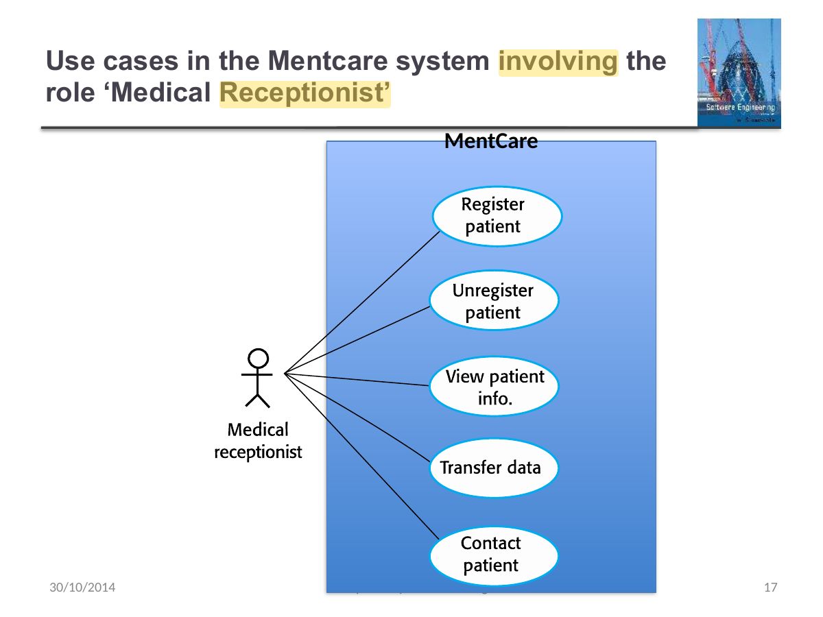
                          Slide 17: Use cases in the Mentcare system involving the role ‘Medical Receptionist’
                          Exam weight Low
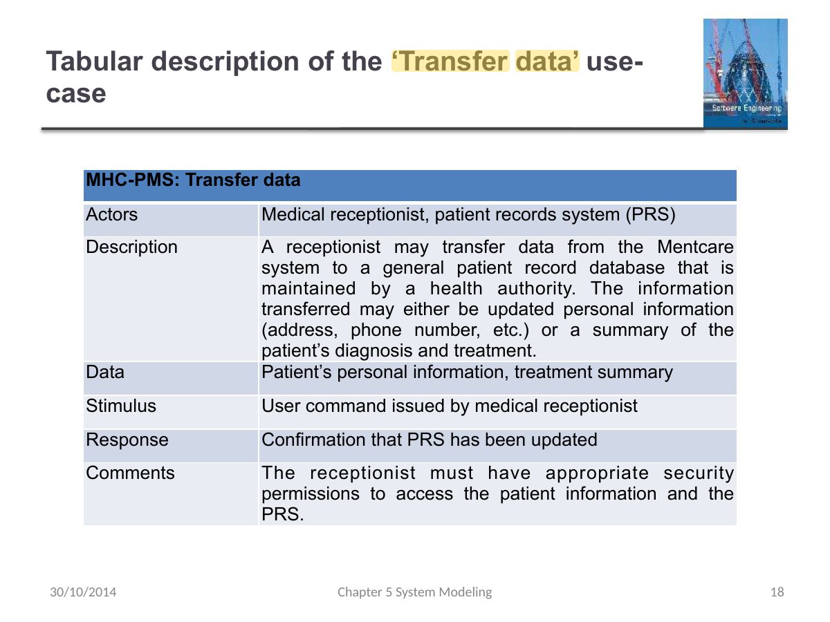
                            Slide 18: Tabular description of the ‘Transfer data’ use- case
                            Exam weight Low

                              Sequence diagrams

                              ◇

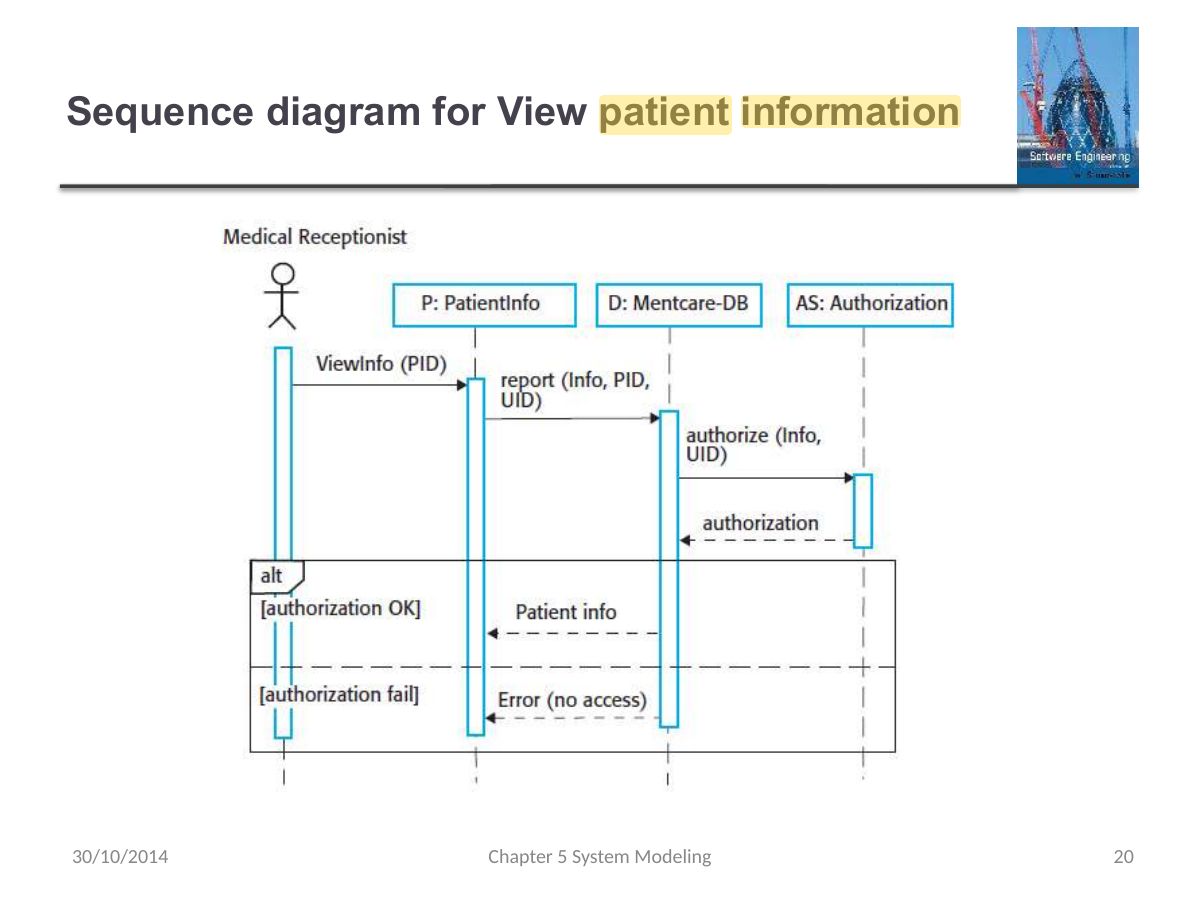
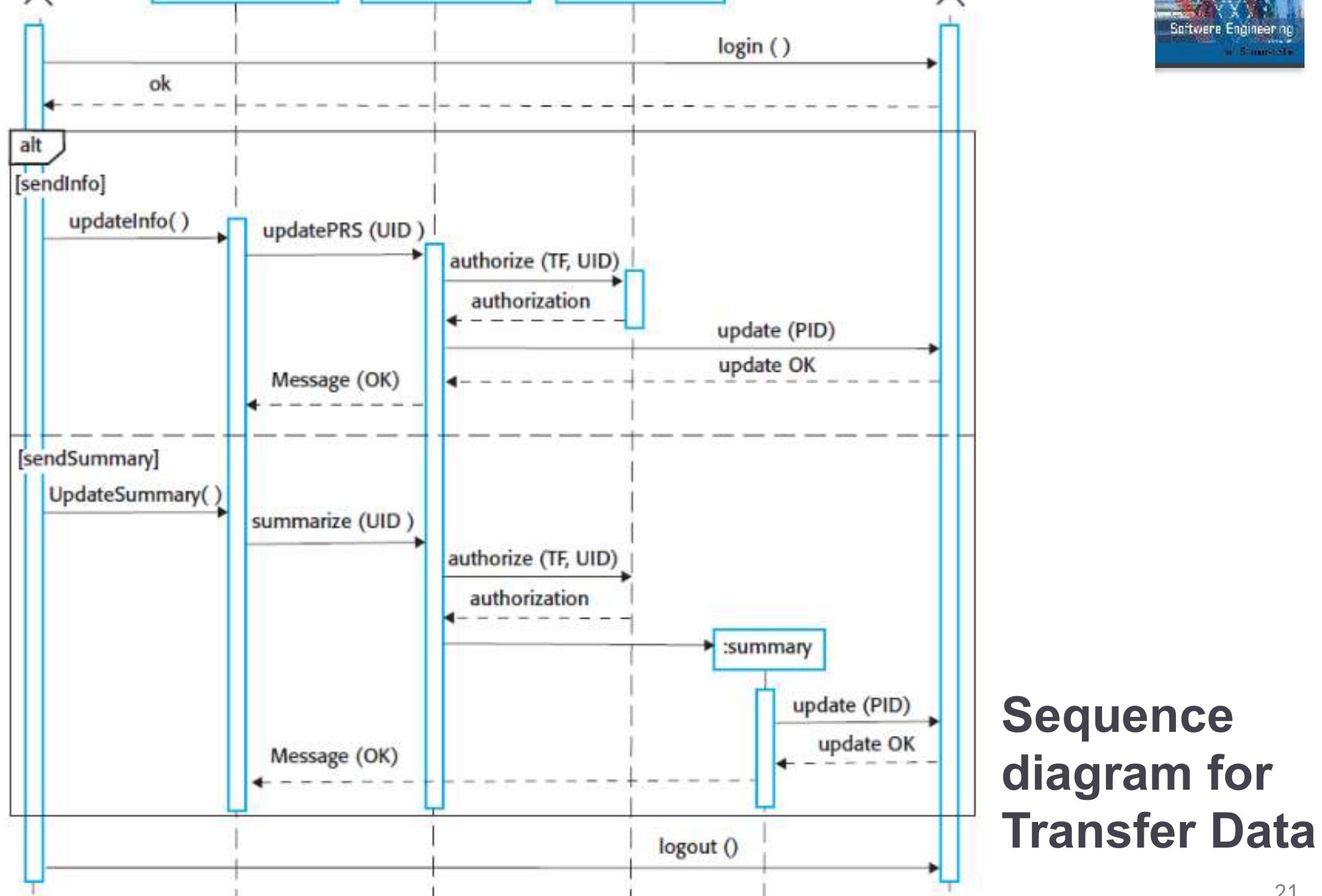
                              Sequence diagrams are part of UML and are used to model the interactions between the actors and the objects within a system.

                              ◇

                              A sequence diagram shows the sequence of interactions that take place during a particular use case or use case instance.

                              ◇

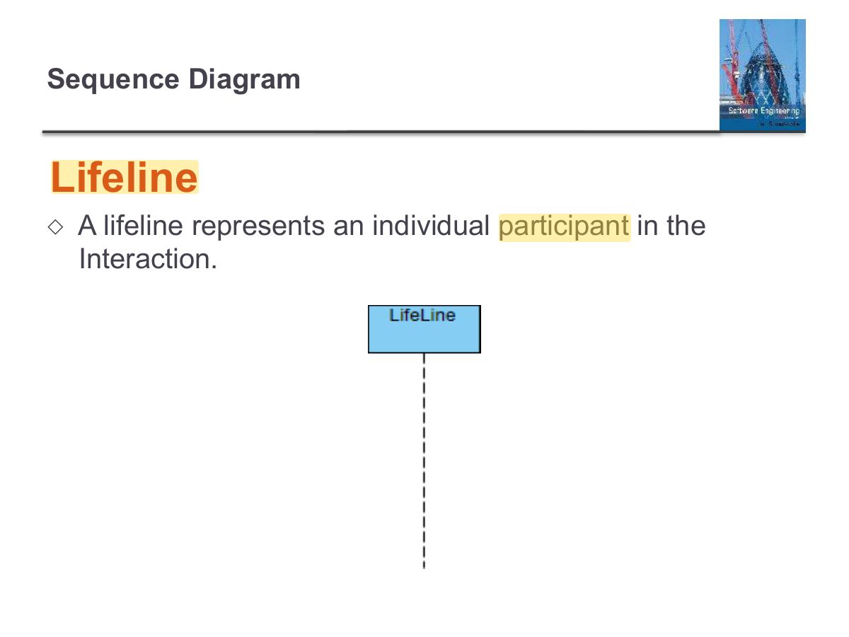
                              The objects and actors involved are listed along the top of the diagram, with a dotted line drawn vertically from these.

                              ◇

                              Interactions between objects are indicated by annotated arrows.

                              30/10/2014

                              Chapter 5 System Modeling

                              Sequence diagrams
                              19
                              Exam weight Low
                              1. Sequence diagram: objects across the top, lifelines down, messages in time order.
                              Slide 20: Sequence diagram for View patient information
                              Exam weight Low

                                Sequence diagram for Transfer Data

                                30/10/2014

                                Chapter 5 System Modeling

                                Slide 21
                                21
                                Exam weight Low

                                  Structural models

                                  30/10/2014

                                  Chapter 5 System Modeling

                                  Slide 22
                                  22
                                  Exam weight Low

                                    Structural models

                                    ◇

                                    Structural models of software display the organization of a system in terms of the components that make up that system and their relationships.

                                    ◇

                                    Structural models may be static models, which show the structure of the system design, or dynamic models, which show the organization of the system when it is executing.

                                    ◇

                                    You create structural models of a system when you are discussing and designing the system architecture.

                                    30/10/2014

                                    Chapter 5 System Modeling

                                    Structural models
                                    23
                                    Exam weight Low

                                      Class diagrams

                                      ◇

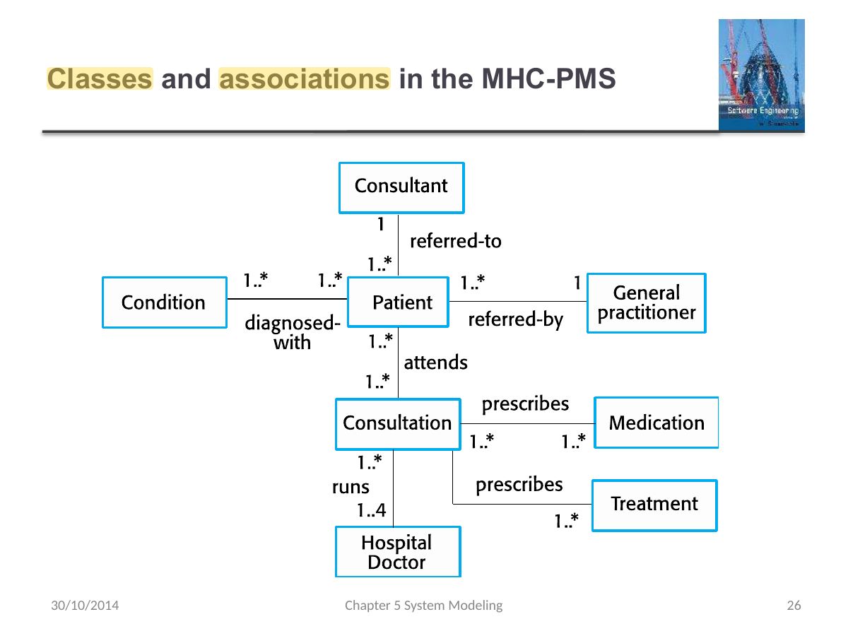
                                      Class diagrams are used when developing an object-oriented system model to show the classes in a system and the associations between these classes.

                                      ◇

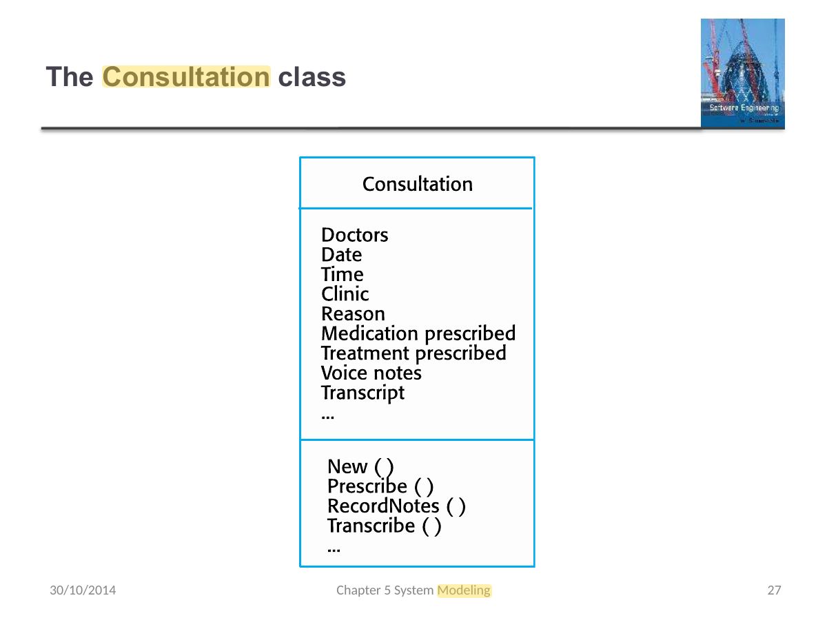
                                      An instance of a class (an object) can be thought of as a general definition of one kind of system object.

                                      ◇

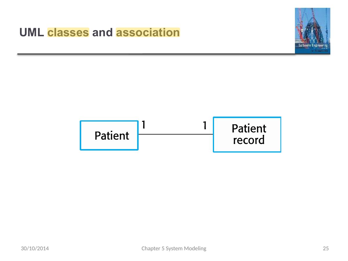
                                      An association is a link between classes that indicates that there is some relationship between these classes.

                                      ◇

                                      When you are developing models during the early stages of the software engineering process, objects represent something in the real world, such as a patient, a prescription, doctor, etc.

                                      30/10/2014

                                      Chapter 5 System Modeling

                                      Class diagrams
                                      24
                                      Exam weight Low
                                      1. Class diagram: classes (name, attributes, operations) and the relationships between them.
                                      Slide 25: UML classes and association
                                      Exam weight Low
                                        Slide 26: Classes and associations in the MHC-PMS
                                        Exam weight Low
                                          Slide 27: The Consultation class
                                          Exam weight Low

                                            Mode detail on

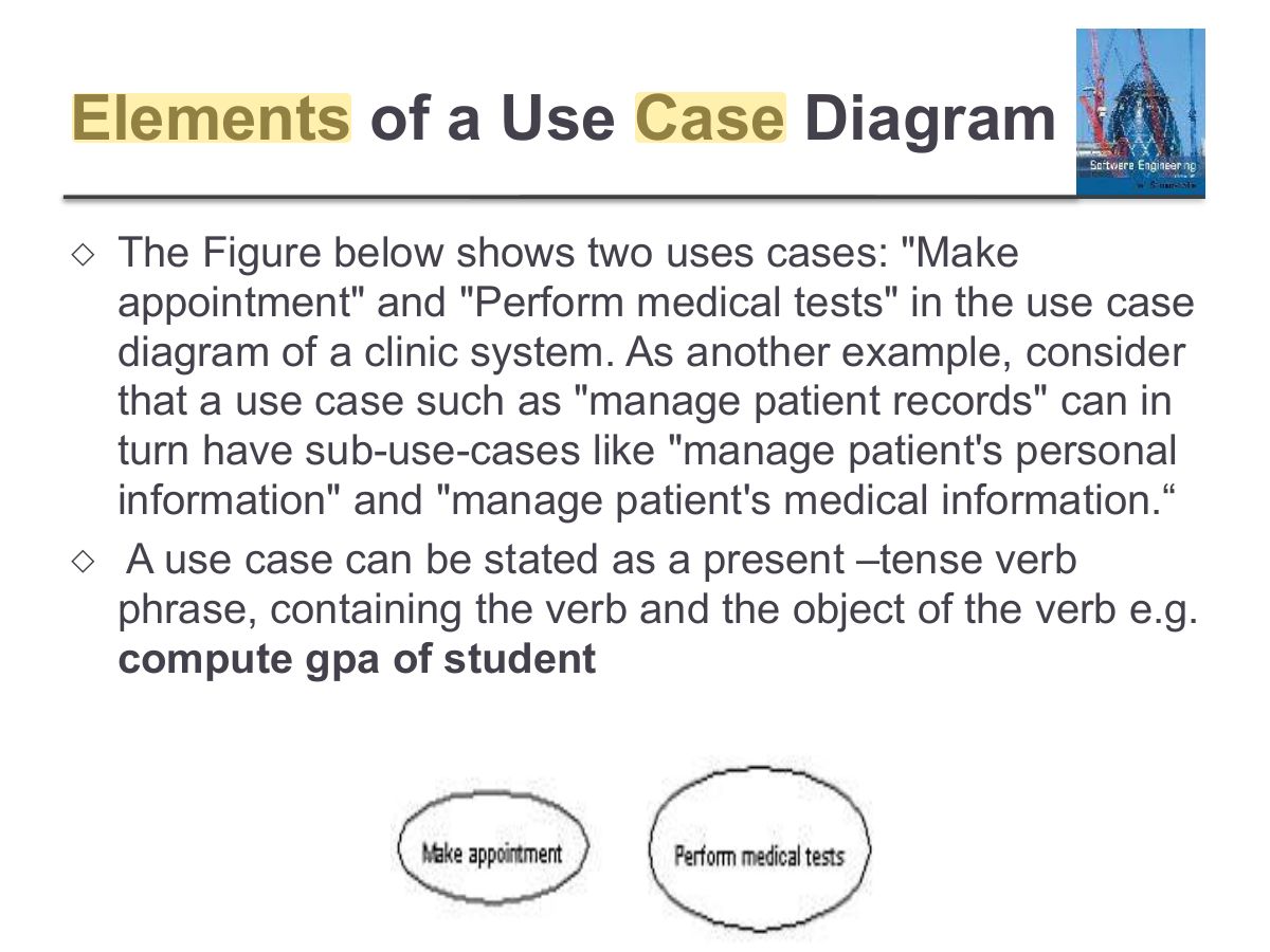
                                            Use Case Diagram

                                            Slide 28
                                            28
                                            Exam weight Low

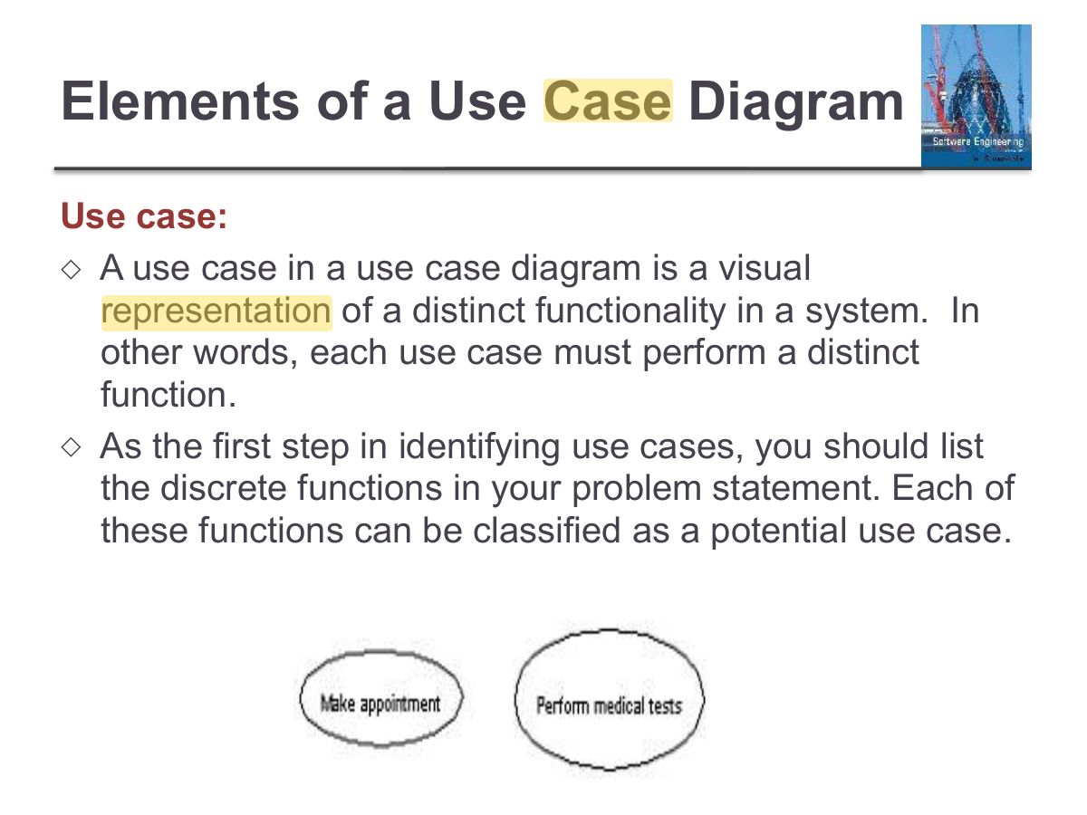
                                              What is a Use case?

                                              “Use cases are a means for specifying required usages of a system. Typically, they are used to capture the requirements of a system.

                                              The key concepts associated with use cases are actors, use cases, and the system under consideration.

                                              The users and any other systems that may interact with the subject are represented as actors. Actors always model entities that are outside the system.

                                              The required behavior of the subject is specified by one or more use cases.

                                              Use cases, actors, and systems are described using use case diagrams.” Source: UML Superstructure Specification v2.4.1 omg.org (summarized)

                                              What is a Use case?
                                              29
                                              Exam weight Low

                                                Elements of a Use Case Diagram

                                                Actors: ◇

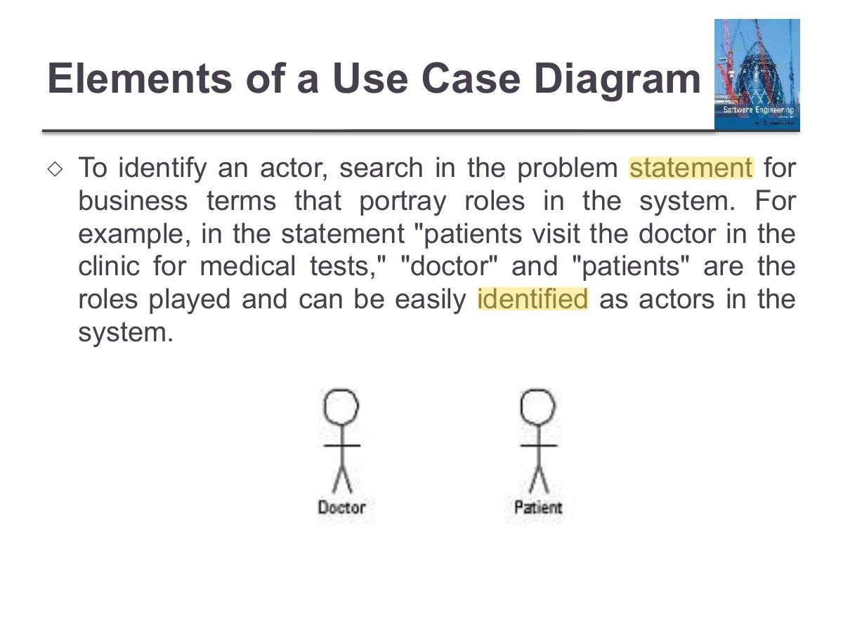
                                                An actor is an external entity, it specifies a role played by a user or any other system that interacts with the system.

                                                ◇

                                                An actor represents any entity (or entities) that exchanges information with the system. An actor in a use case diagram interacts with a use case to accomplish a specific goal.

                                                ◇

                                                For example, for modeling a banking application, a customer entity is represented by an actor in the diagram.

                                                Similarly, the person who provides the service at the counter.

                                                Elements of a Use Case Diagram
                                                30
                                                Exam weight Low
                                                  Slide 31: Elements of a Use Case Diagram
                                                  Exam weight Low
                                                    Slide 32: Elements of a Use Case Diagram
                                                    Exam weight Low
                                                      Slide 33: Elements of a Use Case Diagram
                                                      Exam weight Low

                                                        Elements of a Use Case Diagram

                                                        ◇

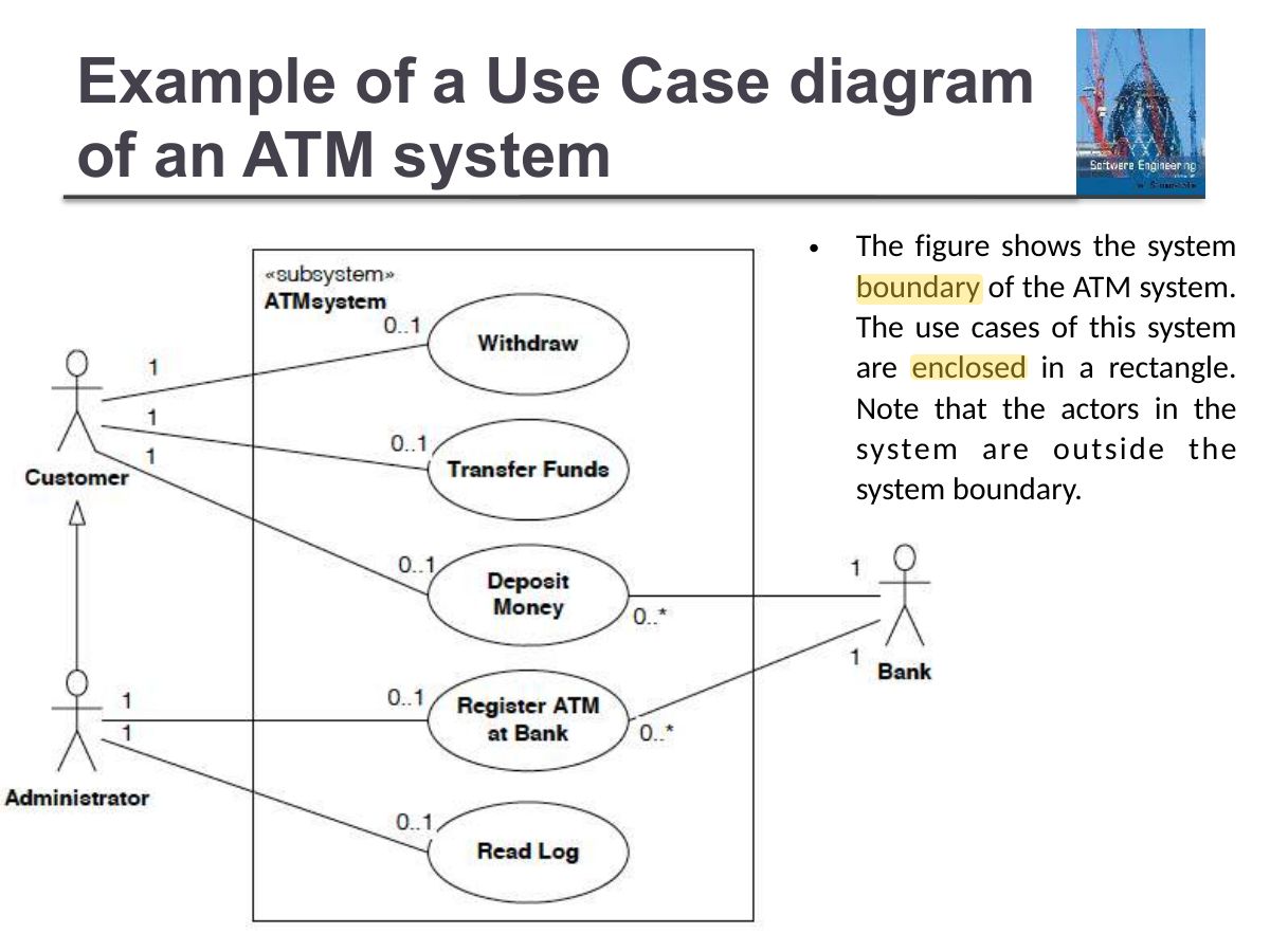
                                                        System boundary: A system boundary defines the scope of what a system will be. A system cannot have infinite functionality. So, it follows that use cases also need to have definitive limits defined. A system boundary of a use case diagram defines the limits of the system. The system boundary is shown as a rectangle spanning all the use cases in the system.

                                                        Elements of a Use Case Diagram
                                                        34
                                                        Exam weight Low
                                                          Slide 35: Example of a Use Case diagram of an ATM system
                                                          Exam weight Low
                                                            Slide 36: Relationships in Use Cases
                                                            Exam weight High
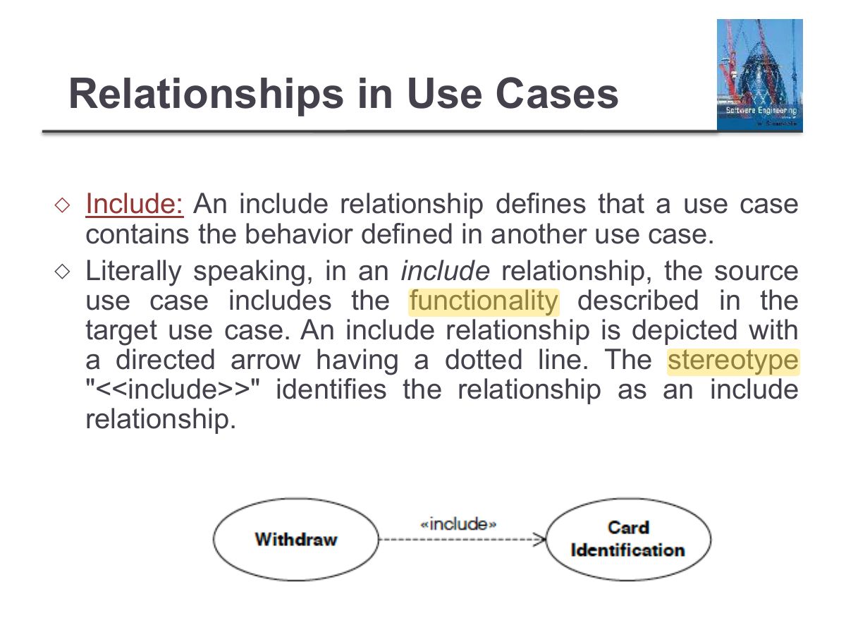
                                                            1. <<include>>: the base use case ALWAYS uses the included one. <<extend>>: optional behaviour that extends the base under a condition.
                                                            Exam trapInclude arrow points TO the included use case; extend arrow points FROM the extension TO the base.
                                                            🎯 How this can come up · 2 questions
                                                            MCQ

                                                            "Print receipt" happens only if the customer asks. Relative to "Withdraw cash" it is:

                                                            MCQ

                                                            Every "Withdraw cash" must "Authenticate user". This is:

                                                            Relationships in Use Cases

                                                            ◇

                                                            Extend: A relationship from an extending use case to an extended use case that specifies how and when the behavior defined in the extending use case can be inserted into the behavior defined in the extended use case.

                                                            ◇

                                                            Extend relationship is also used to design handling exceptions.

                                                            Relationships in Use Cases
                                                            37
                                                            Exam weight Low
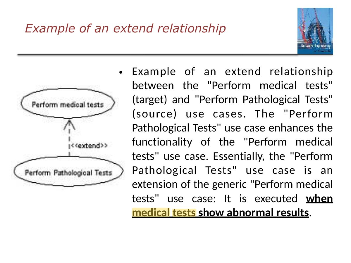
                                                              Slide 38: Example of an extend relationship
                                                              Exam weight Low
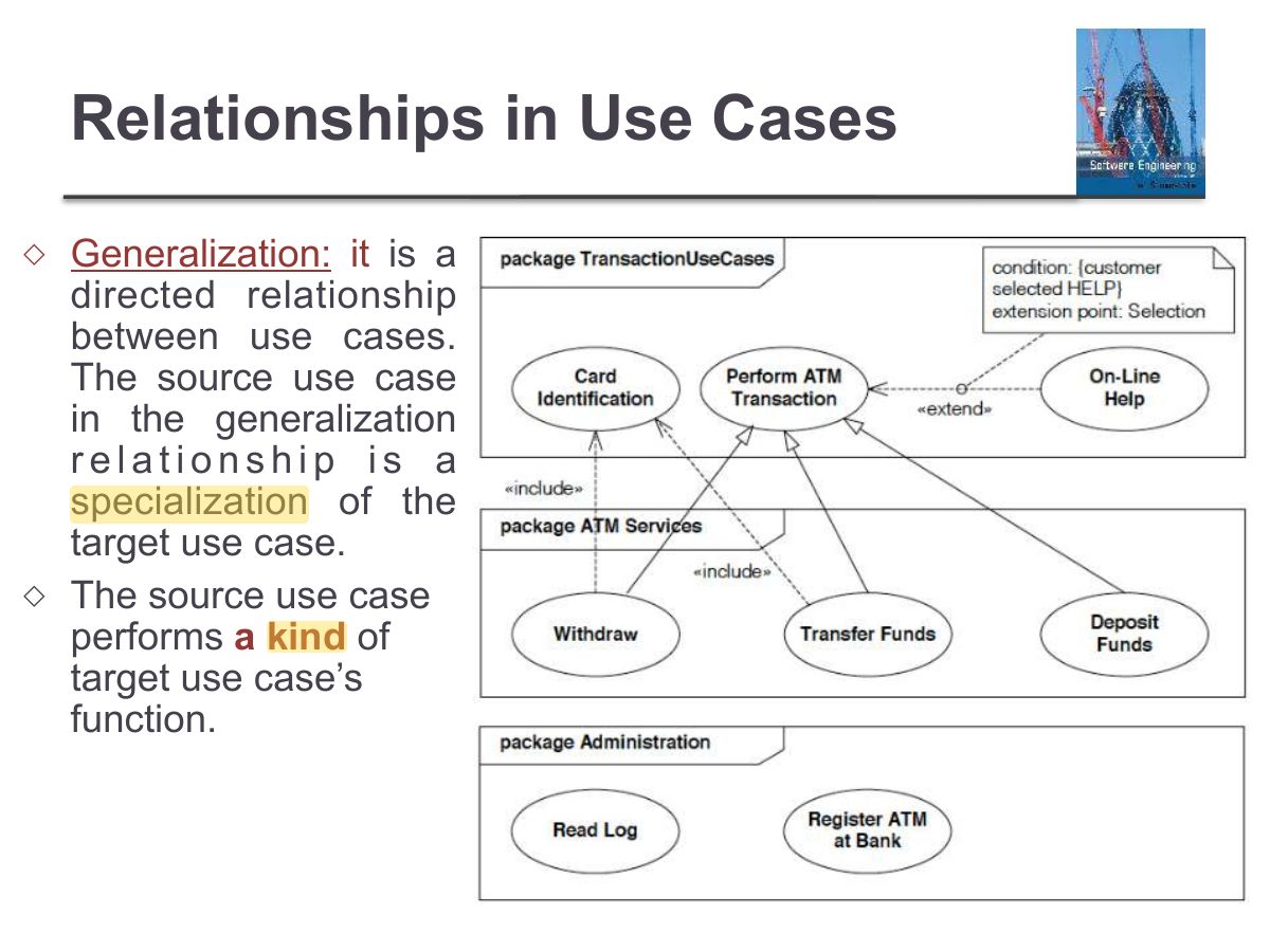
                                                                Slide 39: Relationships in Use Cases
                                                                Exam weight Low

                                                                  Relationships in Use Cases

                                                                  Difference between Generalization and Extension: ◇

                                                                  When you establish a generalization relationship between use cases, this implies that the target use case can be replaced by the source use case. On the other hand, an extend relationship between use cases implies that the source use case enhances the functionality of the target use. The target use case in an extend relationship cannot be replaced by the source use case.

                                                                  Relationships in Use Cases
                                                                  40
                                                                  Exam weight Low

                                                                    Exercise

                                                                    Draw a use case diagram for a university registration system:

                                                                    The system is used by students to register for courses. Assume that the student accesses an electronic course catalog to find out about available courses.

                                                                    Courses may have limited enrollment, so the registration process must include checks that places are available.

                                                                    Students have to complete all pre-requisites of a course before being allowed to register to that course. A student may send a message to the department’s chair to request that the pre-requisite condition be overlooked if he is taking the required course in parallel.

                                                                    Exercise
                                                                    41
                                                                    Exam weight Low

                                                                      Use-case diagram for a university registration system

                                                                      Use-case diagram for a university registration system
                                                                      42
                                                                      Exam weight Low

                                                                        ATM Example

                                                                        ◇ An ATM system has a switch that allows an operator to start and

                                                                        shutdown the system. The operator can configure the system to connect it to the bank system. He can run a maintenance check process that checks that the system is working properly. When a problem is detected, the operator has to solve the problem or request a more specialized maintenance team to solve the problem.

                                                                        The operator has to shut down the system until the other team arrives.

                                                                        ◇ A customer is required to insert his ATM card and enter his PIN. The

                                                                        PIN and card ID will be sent to the bank for validation before any transaction. If the PIN is not valid, then a message “invalid PIN” is displayed. If the PIN is valid, the customer will be able to perform one of the following transactions: make a cash withdrawal, make a deposit, make a money transfer to previously saved accounts, make a balance inquiry.

                                                                        ATM Example
                                                                        43
                                                                        Exam weight Low

                                                                          Sequence Diagram

                                                                          Slide 44
                                                                          44
                                                                          Exam weight Low

                                                                            Interaction Diagrams

                                                                            ◇

                                                                            An Interaction is a behaviour that comprises a set of messages exchanged between a set of objects within a context to accomplish a purpose.

                                                                            ◇

                                                                            A message is a specification of a communication between objects that conveys information.

                                                                            ◇

                                                                            In UML, interaction diagrams are used for the following purposes:

                                                                            • to model the dynamic behavior of a system.
                                                                            • To visualize the communication and sequence of message passing in the system
                                                                            Interaction Diagrams
                                                                            45
                                                                            Exam weight Low
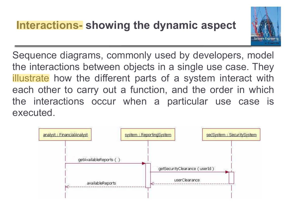
                                                                              Slide 46: Interactions- showing the dynamic aspect
                                                                              Exam weight Low

                                                                                Sequence Diagram

                                                                                ◇

                                                                                A sequence diagram is two dimensional. Graphically a sequence diagram is a table that shows objects arranged along the X-axis and messages ordered in increasing time along the Y-axis.

                                                                                ◇

                                                                                A Sequence Diagram should be modeled for the main scenario of the use case, and frequent or complex alternative scenarios.

                                                                                ◇

                                                                                All systems/components are treated as black boxes

                                                                                Sequence Diagram
                                                                                47
                                                                                Exam weight Low
                                                                                  Slide 48: Sequence Diagram
                                                                                  Exam weight Low

                                                                                    Sequence Diagram

                                                                                    Actor: ◇

                                                                                    An Actor represents a role played by an entity that interacts with the system (e.g., by exchanging signals and data). An actor is external to the subject (i.e., in the sense that an instance of an actor is not a part of the instance of its corresponding subject). They typically represent roles played by human users, external hardware, or other systems.

                                                                                    ◇

                                                                                    Note That:

                                                                                    1. An actor does not necessarily represent a specific physical entity but merely a particular role of some entity
                                                                                    2. A person/component may play the role of several different actors and, conversely, a given actor may be played by different persons.
                                                                                    Sequence Diagram
                                                                                    49
                                                                                    Exam weight Low
                                                                                      Slide 50: Sequence Diagram
                                                                                      Exam weight Low
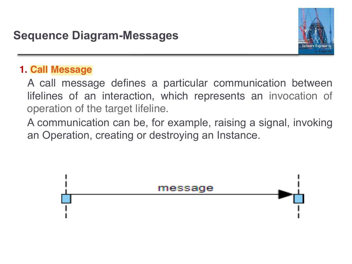
                                                                                        Slide 51: Sequence Diagram-Messages
                                                                                        Exam weight Low
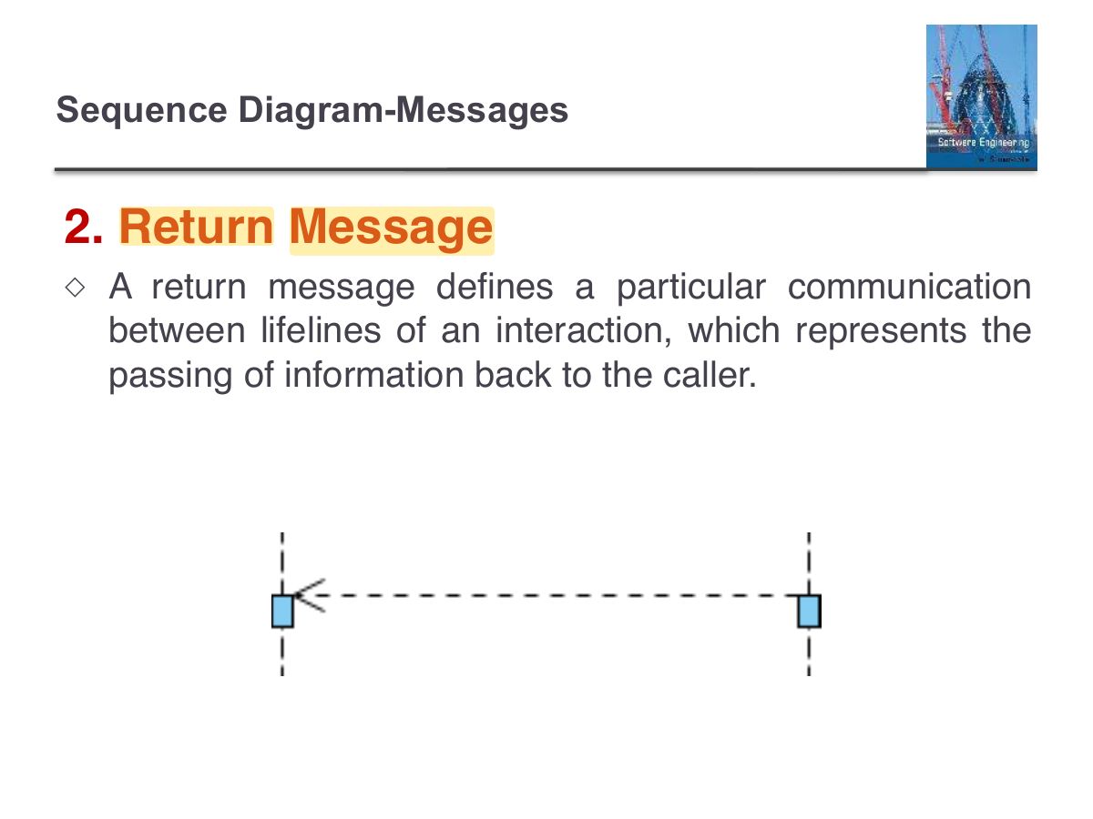
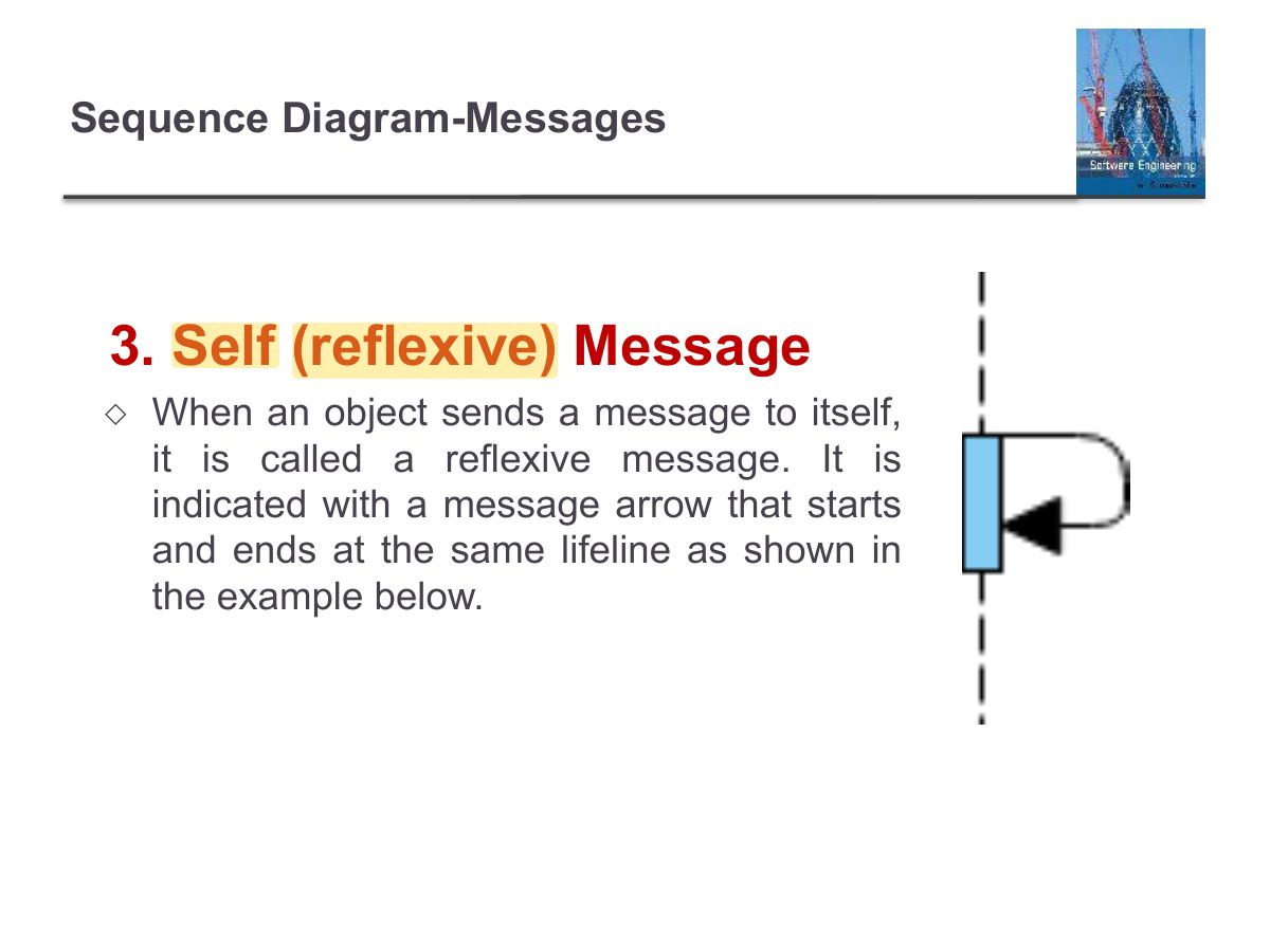
                                                                                        1. Messages: synchronous (filled arrowhead, caller waits), asynchronous (open arrowhead), return (dashed), self-message.
                                                                                        Slide 52: Sequence Diagram-Messages
                                                                                        Exam weight Low
                                                                                          Slide 53: Sequence Diagram-Messages
                                                                                          Exam weight Low

                                                                                            Elements of Sequence Message Arrows

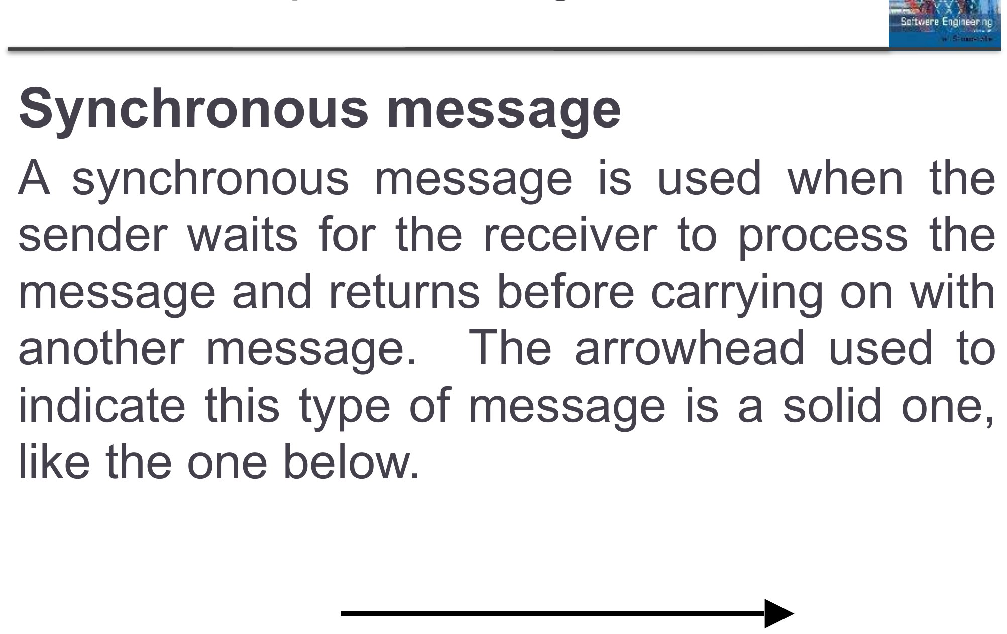
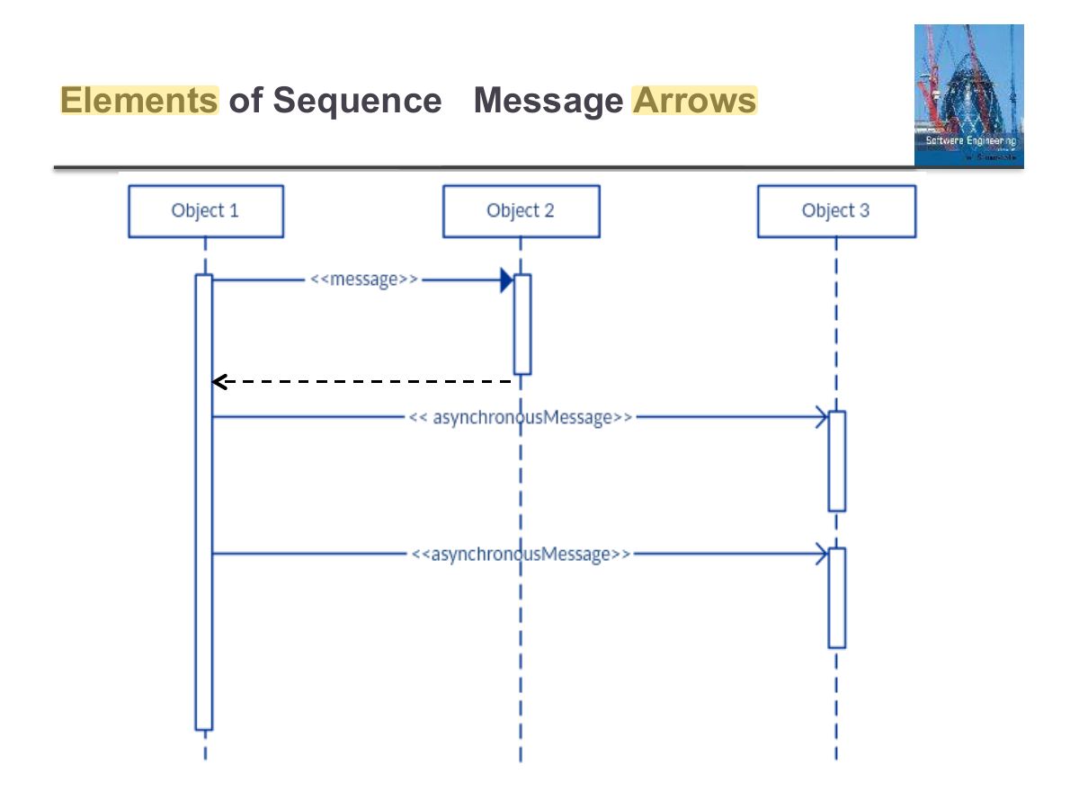
                                                                                            Synchronous message A synchronous message is used when the sender waits for the receiver to process the message and returns before carrying on with another message. The arrowhead used to indicate this type of message is a solid one, like the one below.

                                                                                            Elements of Sequence Message Arrows
                                                                                            54
                                                                                            Exam weight Low

                                                                                              Elements of Sequence Message Arrows

                                                                                              ◇

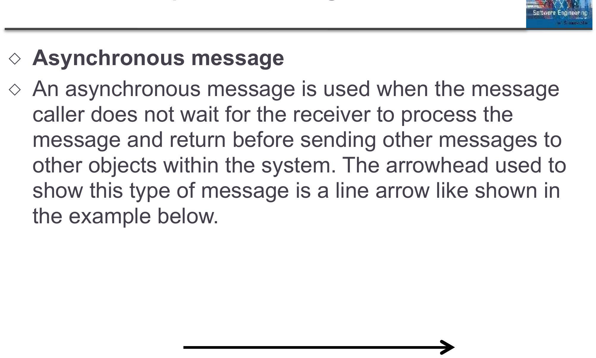
                                                                                              Asynchronous message

                                                                                              ◇

                                                                                              An asynchronous message is used when the message caller does not wait for the receiver to process the message and return before sending other messages to other objects within the system. The arrowhead used to show this type of message is a line arrow like shown in the example below.

                                                                                              Elements of Sequence Message Arrows
                                                                                              55
                                                                                              Exam weight Low
                                                                                                Slide 56: Elements of Sequence Message Arrows
                                                                                                Exam weight Low
                                                                                                  Slide 57: Sequence Diagram
                                                                                                  Exam weight Low

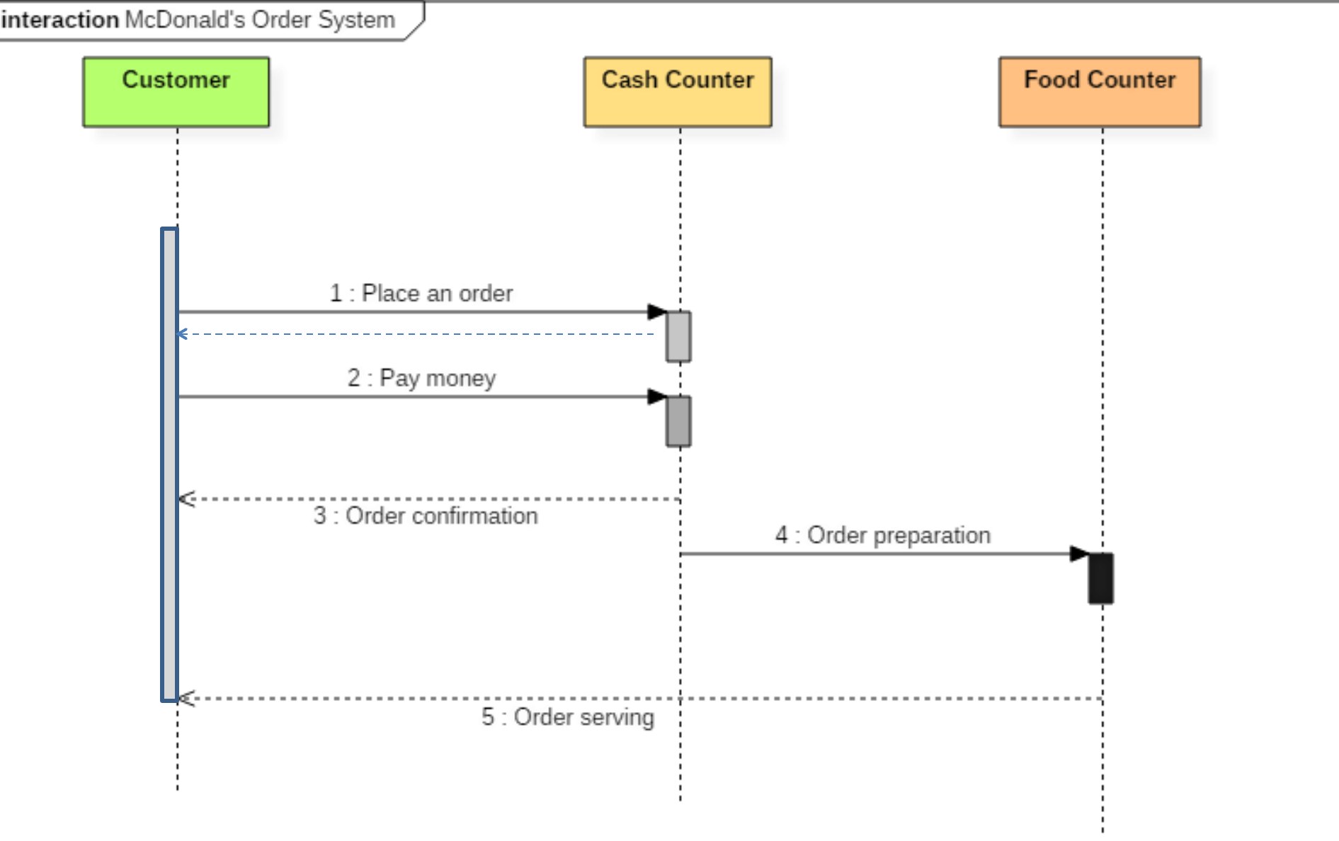
                                                                                                    Sequence diagram of Mcdonald's Ordering System

                                                                                                    ◇

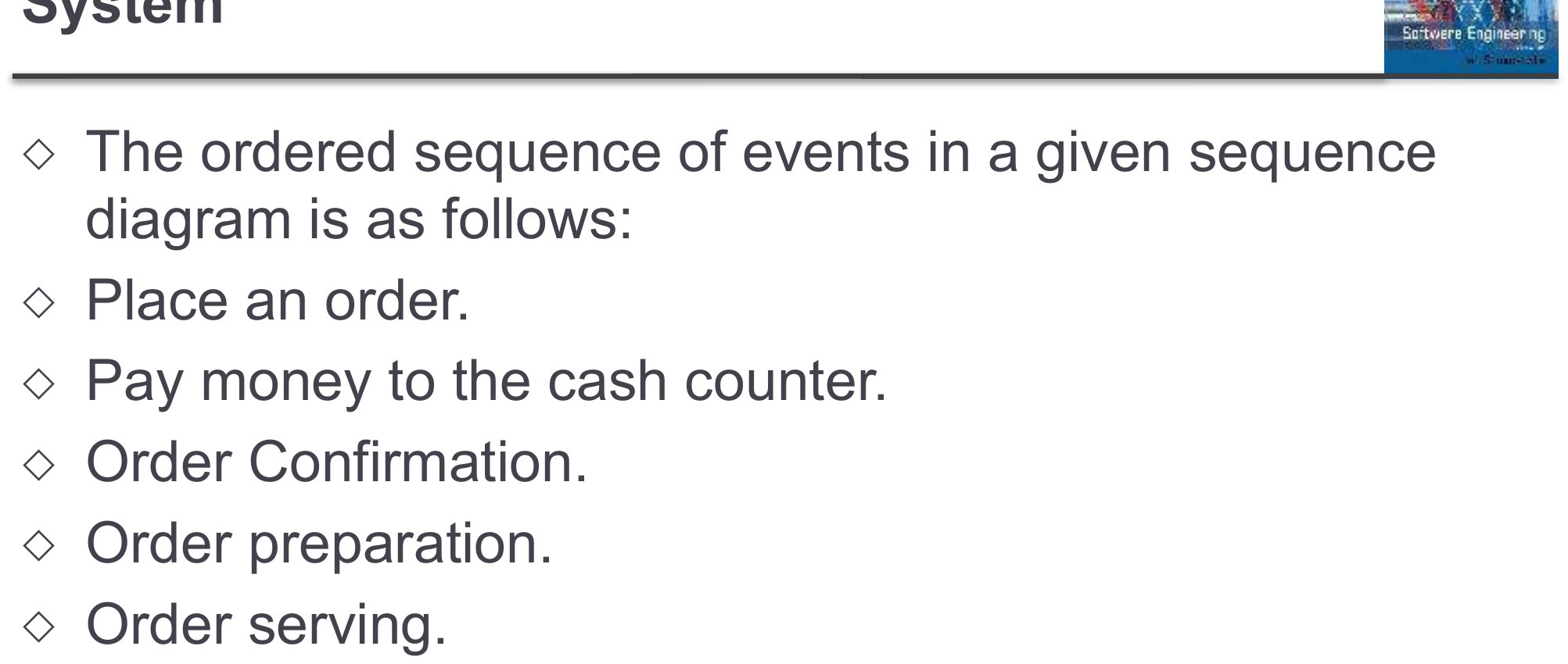
                                                                                                    The ordered sequence of events in a given sequence diagram is as follows:

                                                                                                    ◇

                                                                                                    Place an order.

                                                                                                    ◇

                                                                                                    Pay money to the cash counter.

                                                                                                    ◇

                                                                                                    Order Confirmation.

                                                                                                    ◇

                                                                                                    Order preparation.

                                                                                                    ◇

                                                                                                    Order serving.

                                                                                                    Sequence diagram of Mcdonald's Ordering System
                                                                                                    58
                                                                                                    Exam weight Low

                                                                                                      Mcdonald's Ordering System

                                                                                                      Mcdonald's Ordering System
                                                                                                      59
                                                                                                      Exam weight Low

                                                                                                        Alternatives

                                                                                                        ◇

                                                                                                        Alternatives are used to designate a mutually exclusive choice between two or more message sequences.

                                                                                                        ◇

                                                                                                        Alternatives allow the modeling of the classic “if then

                                                                                                        else” logic (e.g. if I buy three items, then I get 20% off my purchases; else I get 10% off my purchase.)

                                                                                                        Alternatives
                                                                                                        60
                                                                                                        Exam weight Low
                                                                                                        1. alt fragment: alternatives with guards; opt: optional; loop: repetition.

                                                                                                        Alternatives

                                                                                                        ◇

                                                                                                        An alternative combination fragment is drawn using a frame.

                                                                                                        ◇

                                                                                                        The word “alt” is placed inside the frame’s name box.

                                                                                                        ◇

                                                                                                        The larger rectangle is then divided into what UML calls operand.

                                                                                                        ◇

                                                                                                        Operands are separated by a dashed line (one are the messages following “then” path and another are the messages following “else” path).

                                                                                                        ◇

                                                                                                        Each operand is given a guard to test against, and this guard is placed on the top of the operand. If an operand’s guard equates to “true”, then that operand is the operand to follow.

                                                                                                        Alternatives
                                                                                                        61
                                                                                                        Exam weight Low

                                                                                                          Alternatives

                                                                                                          ◇

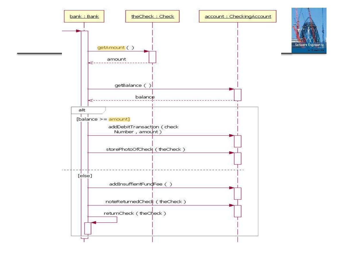
                                                                                                          Fig on the next slide shows the sequence starting at the top, with the bank object getting the check’s amount and the account’s balance.

                                                                                                          ◇

                                                                                                          At this point in the sequence the alternative combination fragment takes over. Because of the guard “[balance >= amount]”, if the account’s balance is greater than or equal to the amount, then the sequence continues with the bank object sending the addDebitTransactrion and storePhotoOfCheck messages to the account object.

                                                                                                          ◇

                                                                                                          However, if the balance is not greater than or equal to the amount, then the sequence proceeds with the bank object sending the addInsufficientFundFee and noteReturned Check message to the account object and the returnCheckmessage to itself. The second sequence is called when the balance is not greater than or equal to the amount because of the “[else]” guard.

                                                                                                          Alternatives
                                                                                                          62
                                                                                                          Exam weight Low
                                                                                                            Slide 63: Slide 63
                                                                                                            Exam weight Low

                                                                                                              Class Diagram

                                                                                                              Slide 64
                                                                                                              64
                                                                                                              Exam weight Low

                                                                                                                Class Diagram

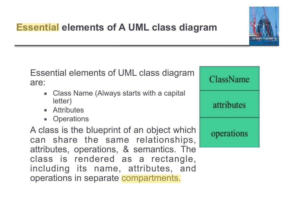
                                                                                                                ◇

                                                                                                                Class diagram is a static diagram. It gives a static view of a system.

                                                                                                                ◇

                                                                                                                Class diagram is not only used for visualizing, describing, and documenting different aspects of a system but also for constructing executable code of the software.

                                                                                                                ◇

                                                                                                                UML Class diagram is a type of structure diagram.

                                                                                                                ◇

                                                                                                                UML Class diagram gives an overview of a software system by displaying classes, attributes, operations, and their relationships.

                                                                                                                Class Diagram
                                                                                                                65
                                                                                                                Exam weight Low
                                                                                                                  Slide 66: Advantages of Class Diagram
                                                                                                                  Exam weight Low
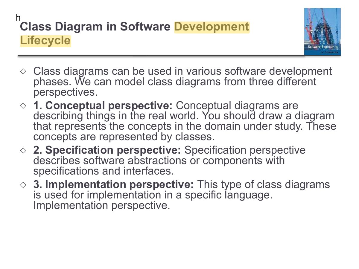
                                                                                                                    Slide 67: h
                                                                                                                    Exam weight Low
                                                                                                                      Slide 68: Essential elements of A UML class diagram
                                                                                                                      Exam weight Low
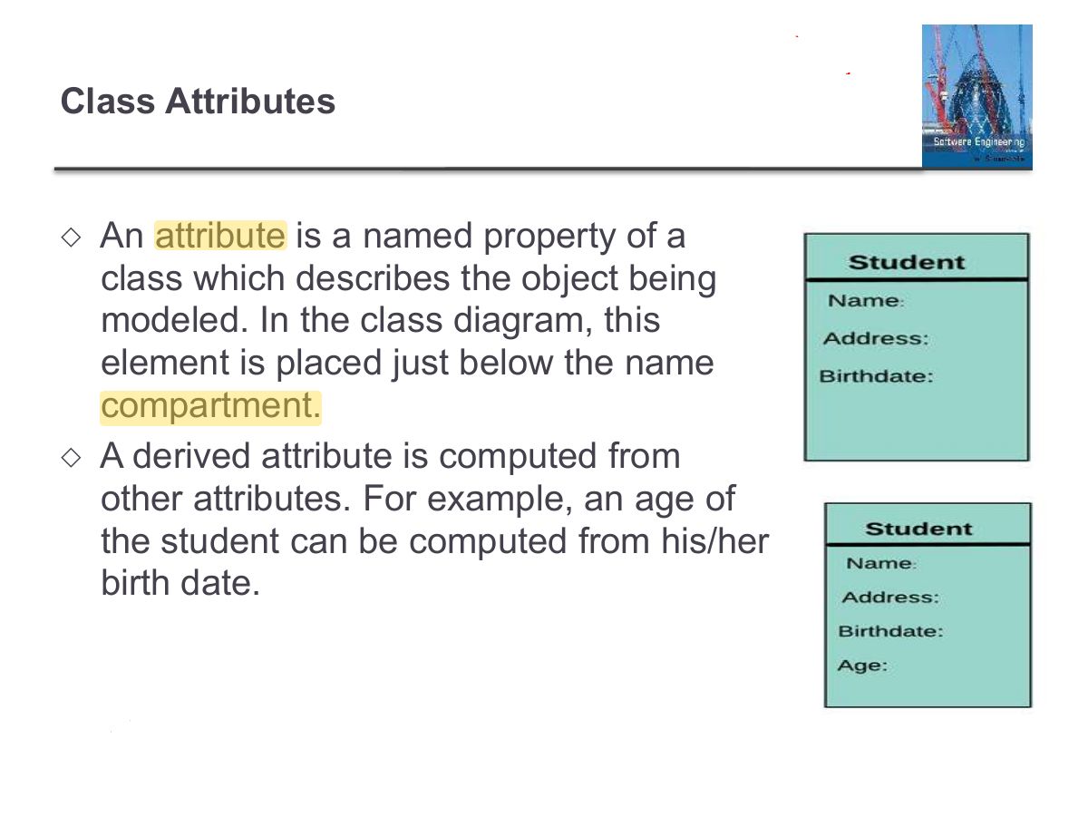
                                                                                                                        Slide 69: Class Attributes
                                                                                                                        Exam weight Low

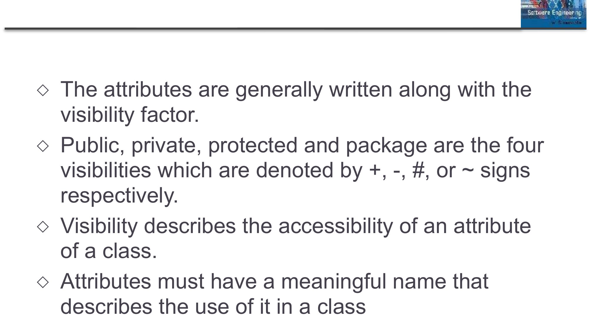
                                                                                                                          Attributes characteristics

                                                                                                                          ◇

                                                                                                                          The attributes are generally written along with the visibility factor.

                                                                                                                          ◇

                                                                                                                          Public, private, protected and package are the four visibilities which are denoted by +, -, #, or ~ signs respectively.

                                                                                                                          ◇

                                                                                                                          Visibility describes the accessibility of an attribute of a class.

                                                                                                                          ◇

                                                                                                                          Attributes must have a meaningful name that describes the use of it in a class

                                                                                                                          Attributes characteristics
                                                                                                                          70
                                                                                                                          Exam weight Low

                                                                                                                            Relationships

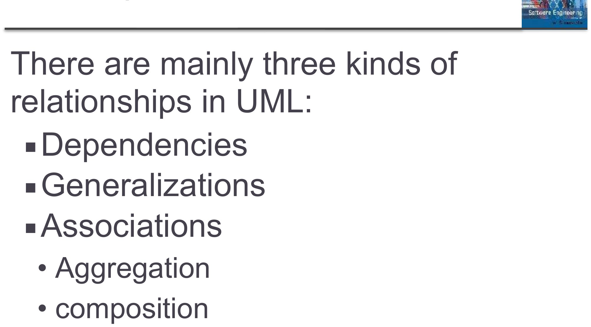
                                                                                                                            There are mainly three kinds of relationships in UML:

                                                                                                                            • Dependencies
                                                                                                                            • Generalizations
                                                                                                                            • Associations
                                                                                                                              • Aggregation
                                                                                                                              • composition
                                                                                                                            Relationships
                                                                                                                            71
                                                                                                                            Exam weight Low
                                                                                                                            1. Relationships: dependency (dashed arrow), association (line), generalization (hollow triangle), aggregation (hollow diamond), composition (filled diamond).
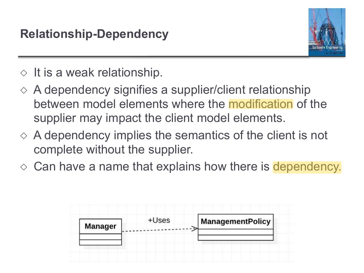
                                                                                                                            Slide 72: Relationship-Dependency
                                                                                                                            Exam weight Low
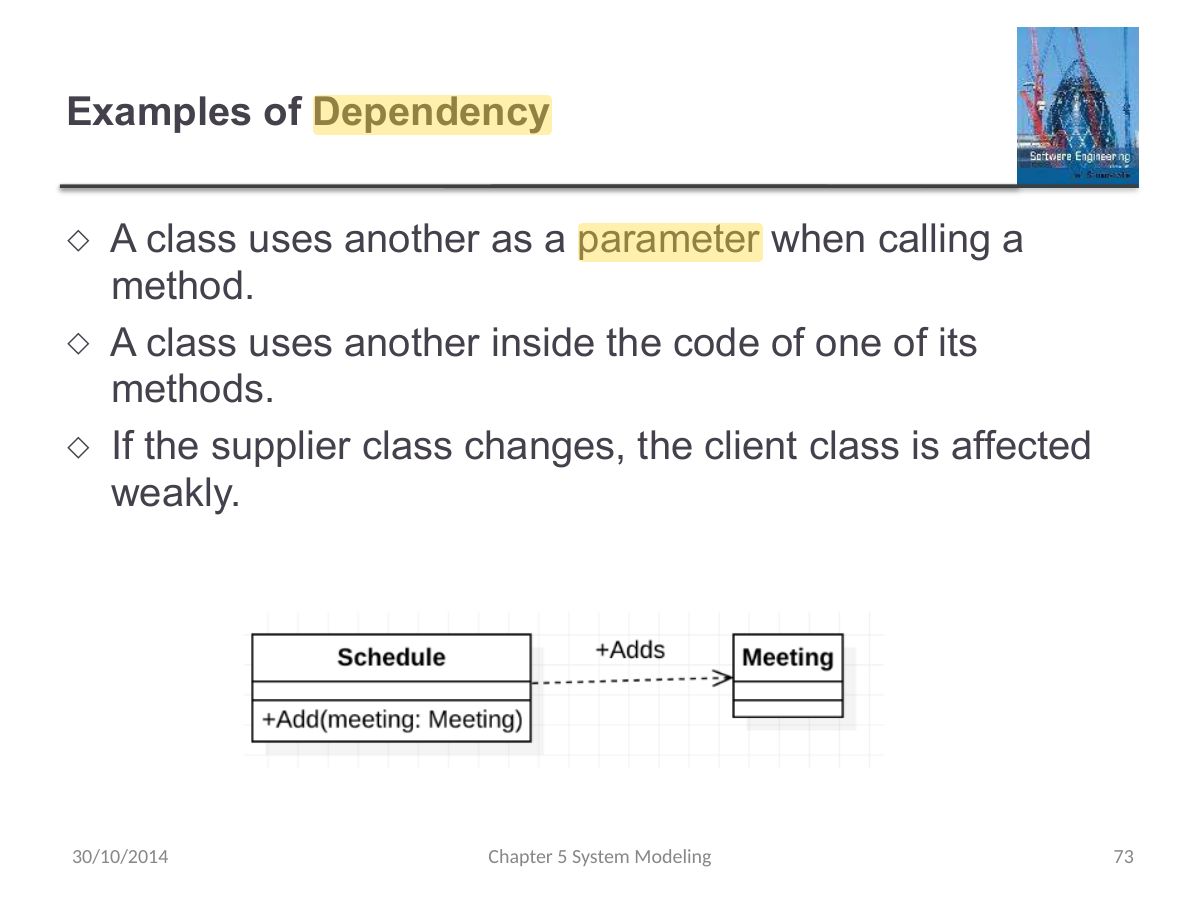
                                                                                                                              Slide 73: Examples of Dependency
                                                                                                                              Exam weight Low
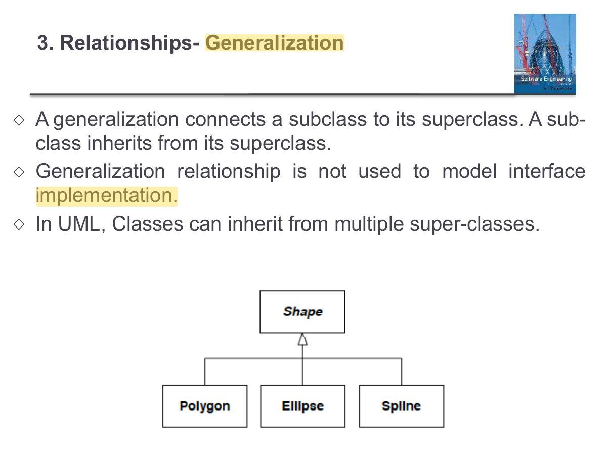
                                                                                                                                Slide 74: 3. Relationships- Generalization
                                                                                                                                Exam weight Low
                                                                                                                                1. Generalization = inheritance ("is-a"): hollow triangle points to the parent.
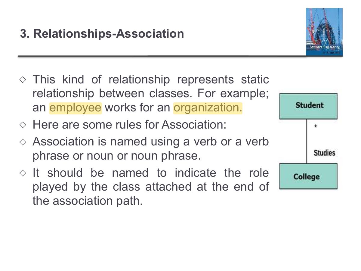
                                                                                                                                Slide 75: 3. Relationships-Association
                                                                                                                                Exam weight High
                                                                                                                                1. Multiplicity: 1, 0..1, *, 1..* at each end of an association.
                                                                                                                                🎯 How this can come up · 1 question
                                                                                                                                MCQ

                                                                                                                                A multiplicity of 1..* means:

                                                                                                                                3. Relationships-Association(Multiplicity)

                                                                                                                                ◇

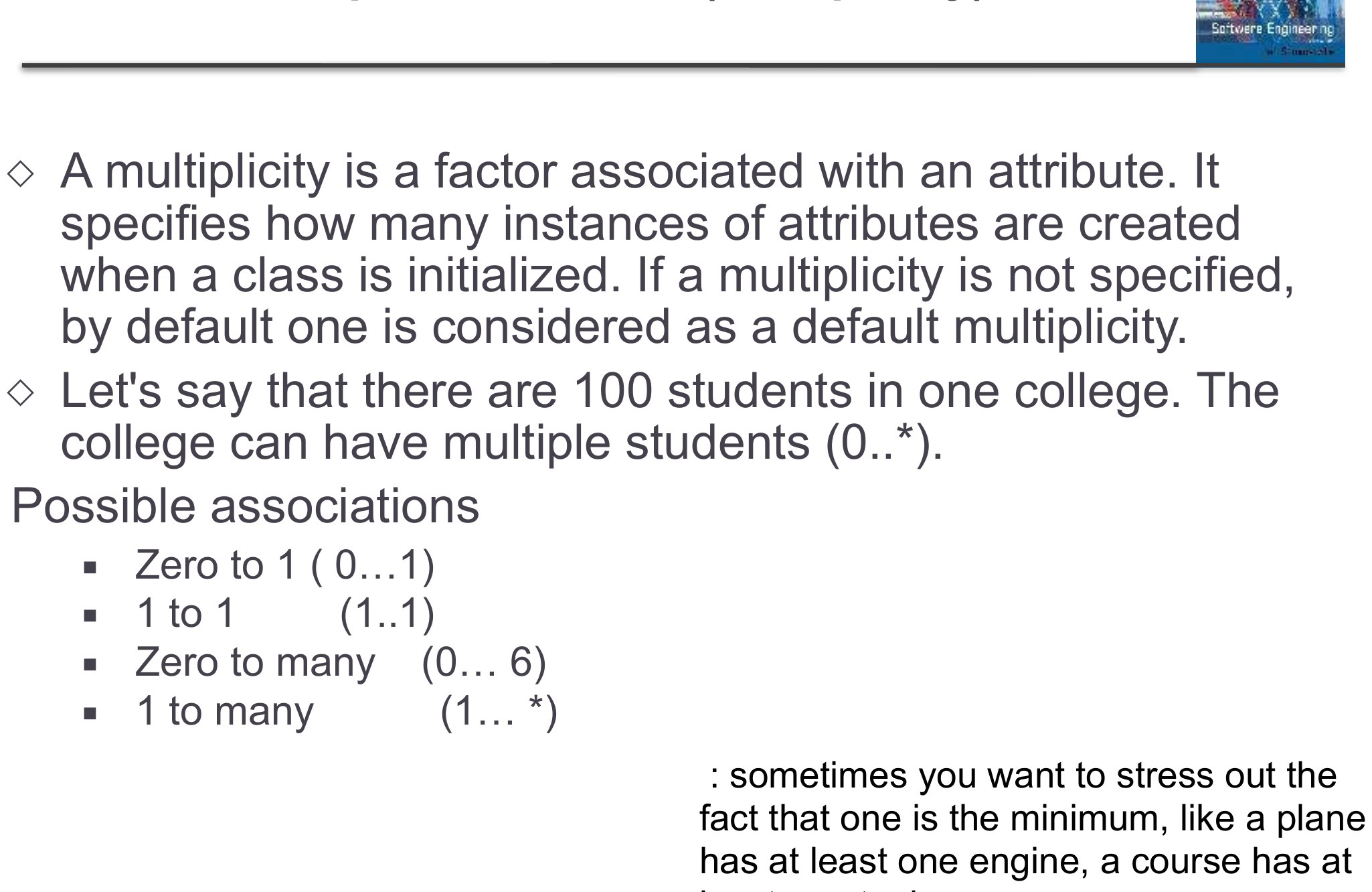
                                                                                                                                A multiplicity is a factor associated with an attribute. It specifies how many instances of attributes are created when a class is initialized. If a multiplicity is not specified, by default one is considered as a default multiplicity.

                                                                                                                                ◇

                                                                                                                                Let's say that there are 100 students in one college. The college can have multiple students (0..*).

                                                                                                                                Possible associations

                                                                                                                                • Zero to 1 (0…1)
                                                                                                                                • 1 to 1 (1..1)
                                                                                                                                • Zero to many (0… 6)
                                                                                                                                • 1 to many (1… *) : sometimes you want to stress out the fact that one is the minimum, like a plane has at least one engine, a course has at
                                                                                                                                3. Relationships-Association(Multiplicity)
                                                                                                                                76
                                                                                                                                Exam weight Low

                                                                                                                                  3. Relationships- Aggregation

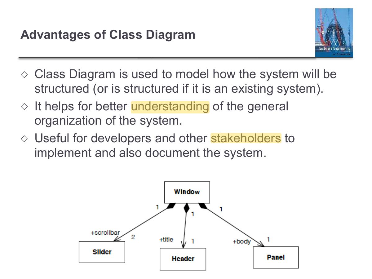
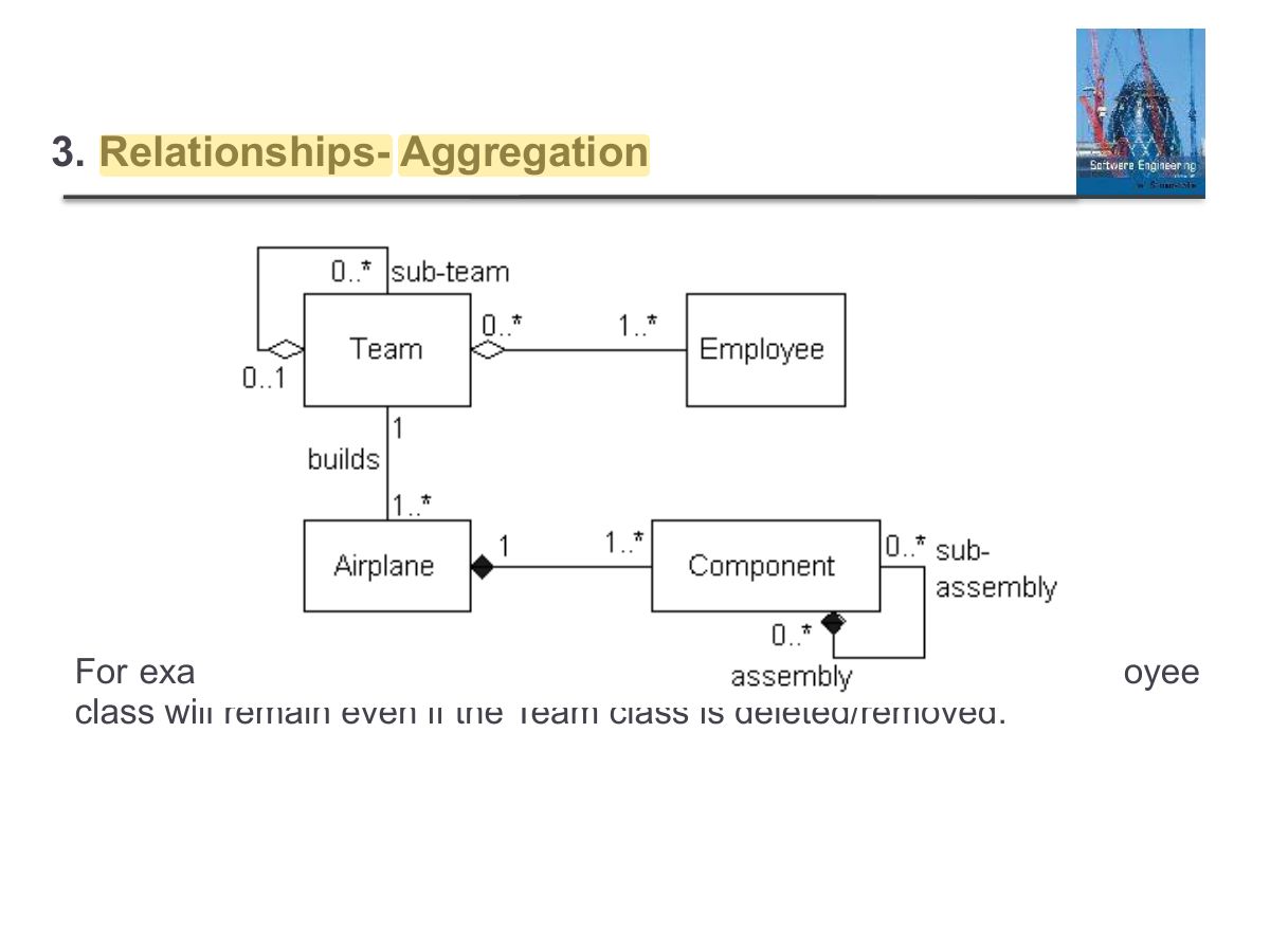
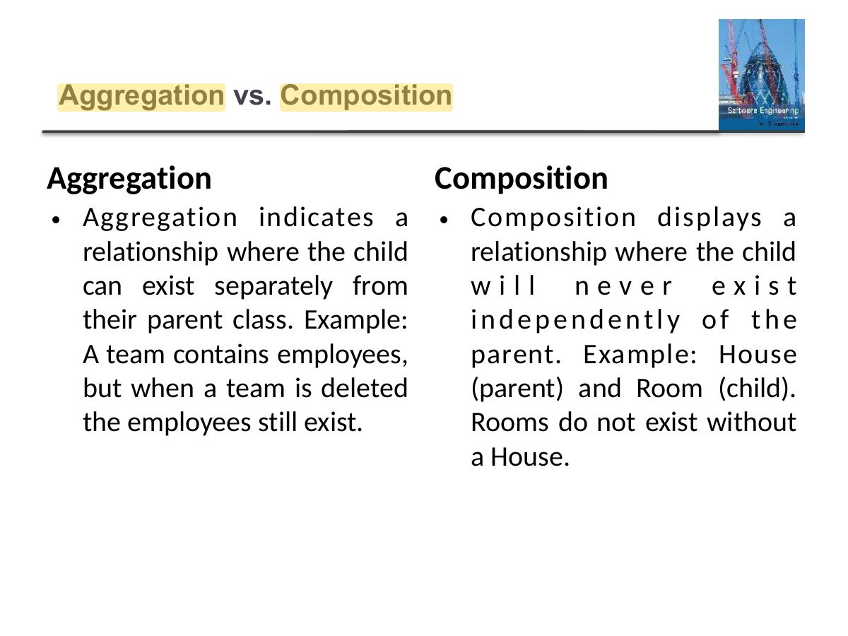
                                                                                                                                  Aggregation is a special type of association that models a whole-part relationship between aggregate and its parts.

                                                                                                                                  In an aggregation relationship, the part object remains even when

                                                                                                                                  the whole object is destroyed.

                                                                                                                                  Aggregation relationship is denoted using a straight line with an empty arrowhead at one end.

                                                                                                                                  3. Relationships- Aggregation
                                                                                                                                  77
                                                                                                                                  Exam weight Low
                                                                                                                                    Slide 78: 3. Relationships- Aggregation
                                                                                                                                    Exam weight Low

                                                                                                                                      Relationship- Composition

                                                                                                                                      ◇

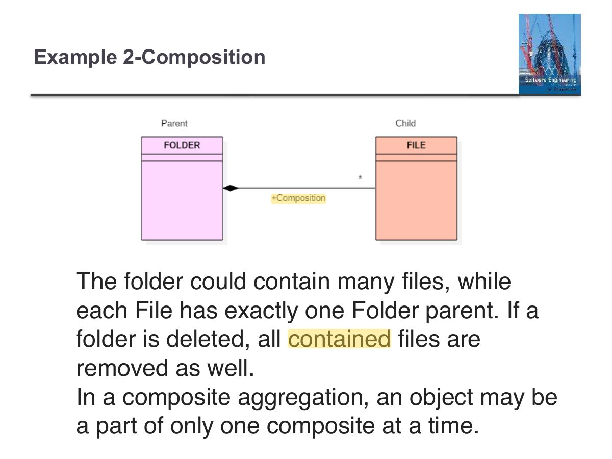
                                                                                                                                      The composition is a special type of association which denotes strong ownership between two classes when one class is a part of another class.

                                                                                                                                      ◇

                                                                                                                                      It is a two-way association between the objects.

                                                                                                                                      ◇

                                                                                                                                      It is a whole/part relationship.

                                                                                                                                      ◇

                                                                                                                                      If a composite is deleted, all other parts associated with it are deleted.

                                                                                                                                      ◇

                                                                                                                                      Composition is described as an association decorated with a filled black diamond at the aggregate (whole) end.

                                                                                                                                      Relationship- Composition
                                                                                                                                      79
                                                                                                                                      Exam weight Low
                                                                                                                                        Slide 80: Example 2-Composition
                                                                                                                                        Exam weight Low
                                                                                                                                          Slide 81: Aggregation vs. Composition
                                                                                                                                          Exam weight High
                                                                                                                                          1. Aggregation: whole–part where parts can exist alone (Department–Professor). Composition: parts die with the whole (House–Room).
                                                                                                                                          Memory trickFilled diamond = "dies with" (composition). Hollow diamond = "can live without" (aggregation).
                                                                                                                                          🎯 How this can come up · 1 question
                                                                                                                                          MCQ

                                                                                                                                          An Order and its OrderLines (deleted with the order) is best modeled as:

                                                                                                                                          Slide 82: Association Class
                                                                                                                                          Exam weight Low
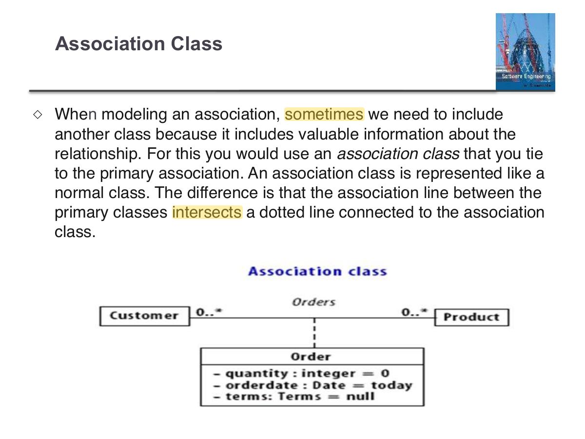
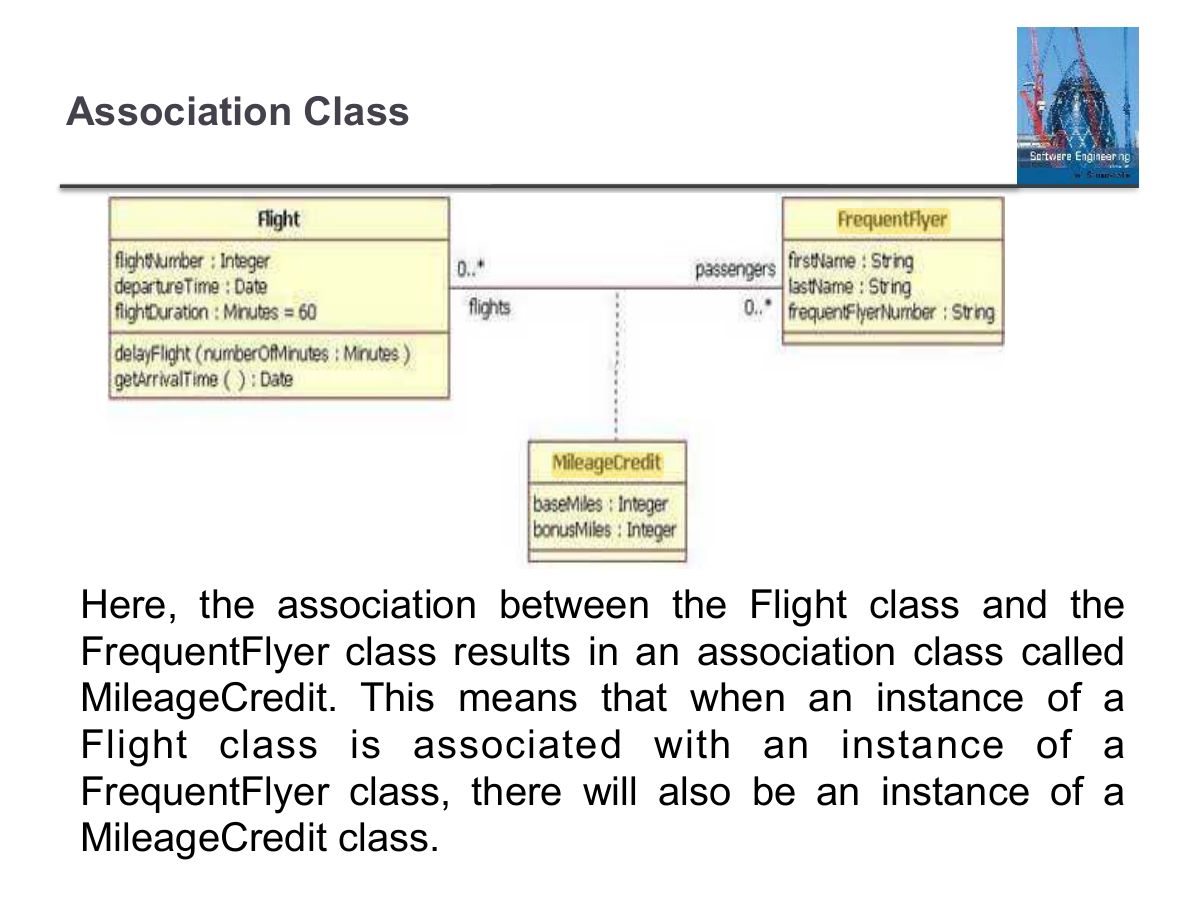
                                                                                                                                          1. Association class: attributes that belong to the link itself (Enrollment with grade between Student and Course).
                                                                                                                                          Slide 83: Association Class
                                                                                                                                          Exam weight Low
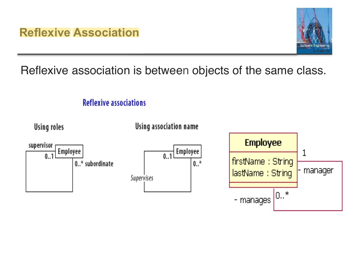
                                                                                                                                            Slide 84: Reflexive Association
                                                                                                                                            Exam weight Low
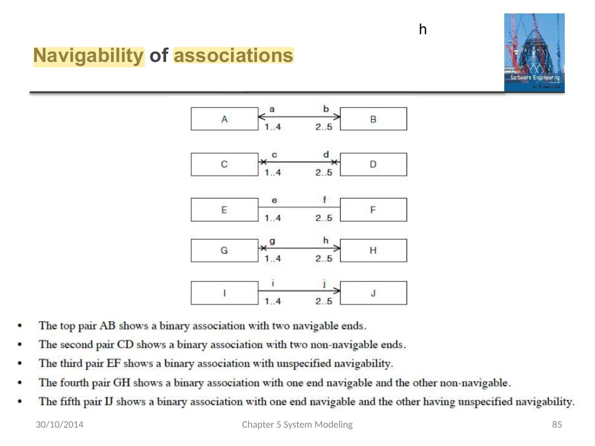
                                                                                                                                              Slide 85: h
                                                                                                                                              Exam weight Low

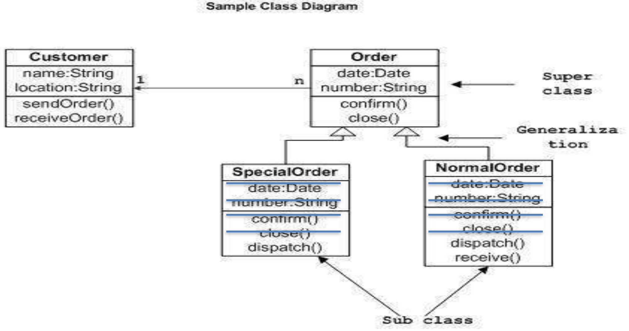
                                                                                                                                                Example of UML Class Diagram

                                                                                                                                                Example of UML Class Diagram
                                                                                                                                                86
                                                                                                                                                Exam weight Low

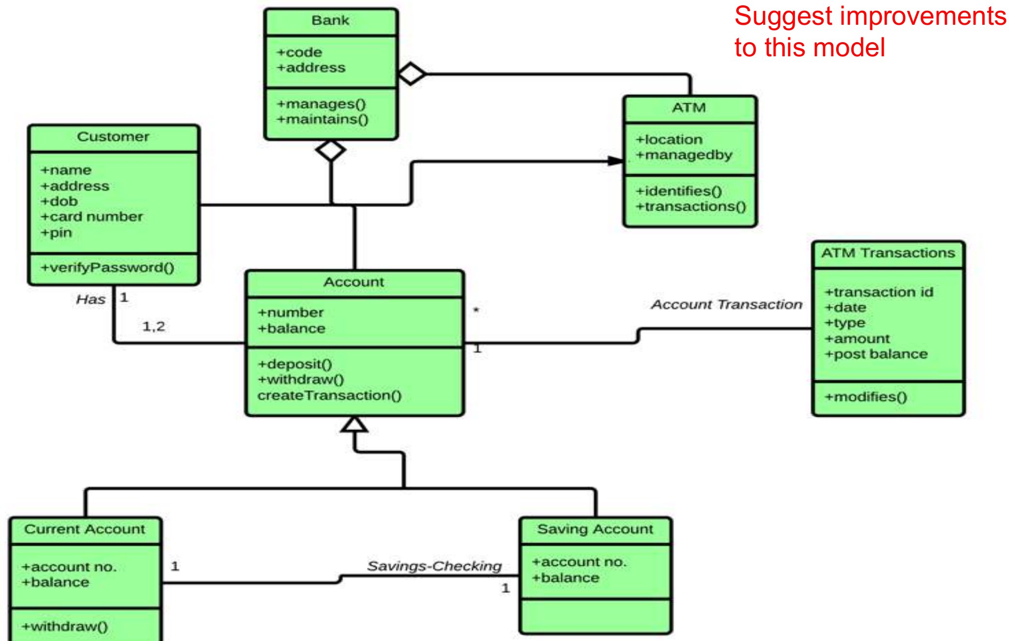
                                                                                                                                                  Exercise on UML Class Diagrams

                                                                                                                                                  Exercise on UML Class Diagrams
                                                                                                                                                  87
                                                                                                                                                  Exam weight Low

                                                                                                                                                    Best practices of Designing of the Class Diagram

                                                                                                                                                    ◇

                                                                                                                                                    Here are some points which should be kept in mind while drawing a class diagram:

                                                                                                                                                    • The name given to classes in a diagram must be meaningful.
                                                                                                                                                    • The relationships between elements need to be identified and specified precisely (naming association ends, multiplicity, navigability).
                                                                                                                                                    • The responsibility for every class needs to be identified.
                                                                                                                                                    • For every class, a minimum number of properties should be specified.
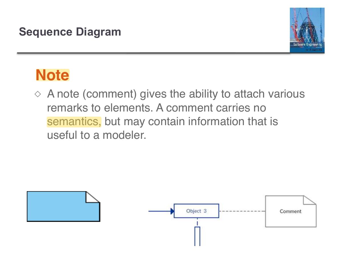
                                                                                                                                                    • User notes should be included whenever you need to clarify some gray areas of the diagram.
                                                                                                                                                    Best practices of Designing of the Class Diagram
                                                                                                                                                    88
                                                                                                                                                    Exam weight Low

                                                                                                                                                      Behavioral Models

                                                                                                                                                      30/10/2014

                                                                                                                                                      Chapter 5 System Modeling

                                                                                                                                                      Slide 89
                                                                                                                                                      89
                                                                                                                                                      Exam weight Low

                                                                                                                                                        What is an Activity diagram?

                                                                                                                                                        ◇

                                                                                                                                                        A UML activity diagram helps to visualize a certain use case at a more detailed level. It is a behavioral diagram that illustrates the flow of activities through a system.

                                                                                                                                                        ◇

                                                                                                                                                        UML activity diagrams can also be used to depict a flow of events in a business process. They can be used to examine business processes in order to identify its flow and requirements.

                                                                                                                                                        ◇

                                                                                                                                                        Activity diagram is another important behavioral diagram in UML diagram to describe dynamic aspects of the system.

                                                                                                                                                        What is an Activity diagram?
                                                                                                                                                        90
                                                                                                                                                        Exam weight Low
                                                                                                                                                        1. Activity diagram: workflow of actions; initial node, actions, decisions (diamond), fork/join bars, final node.
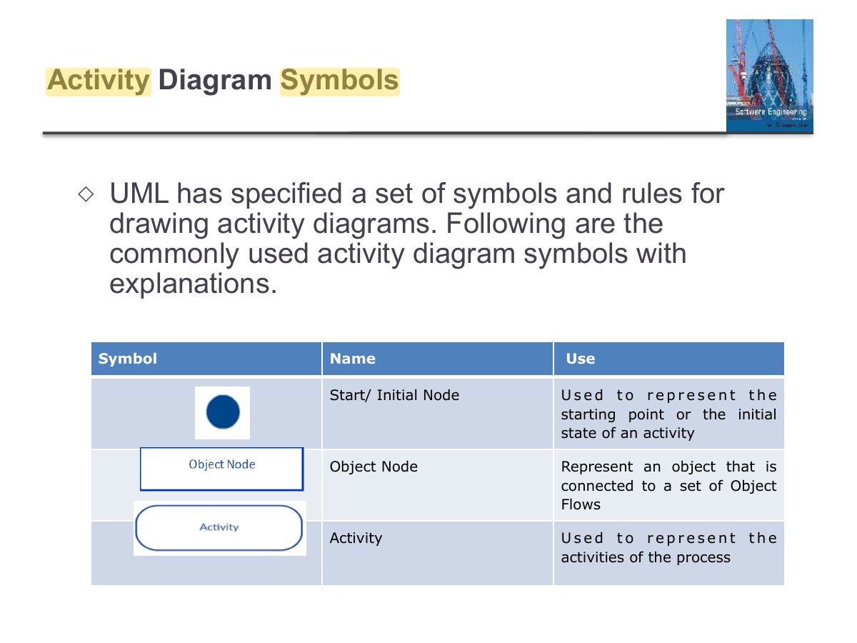
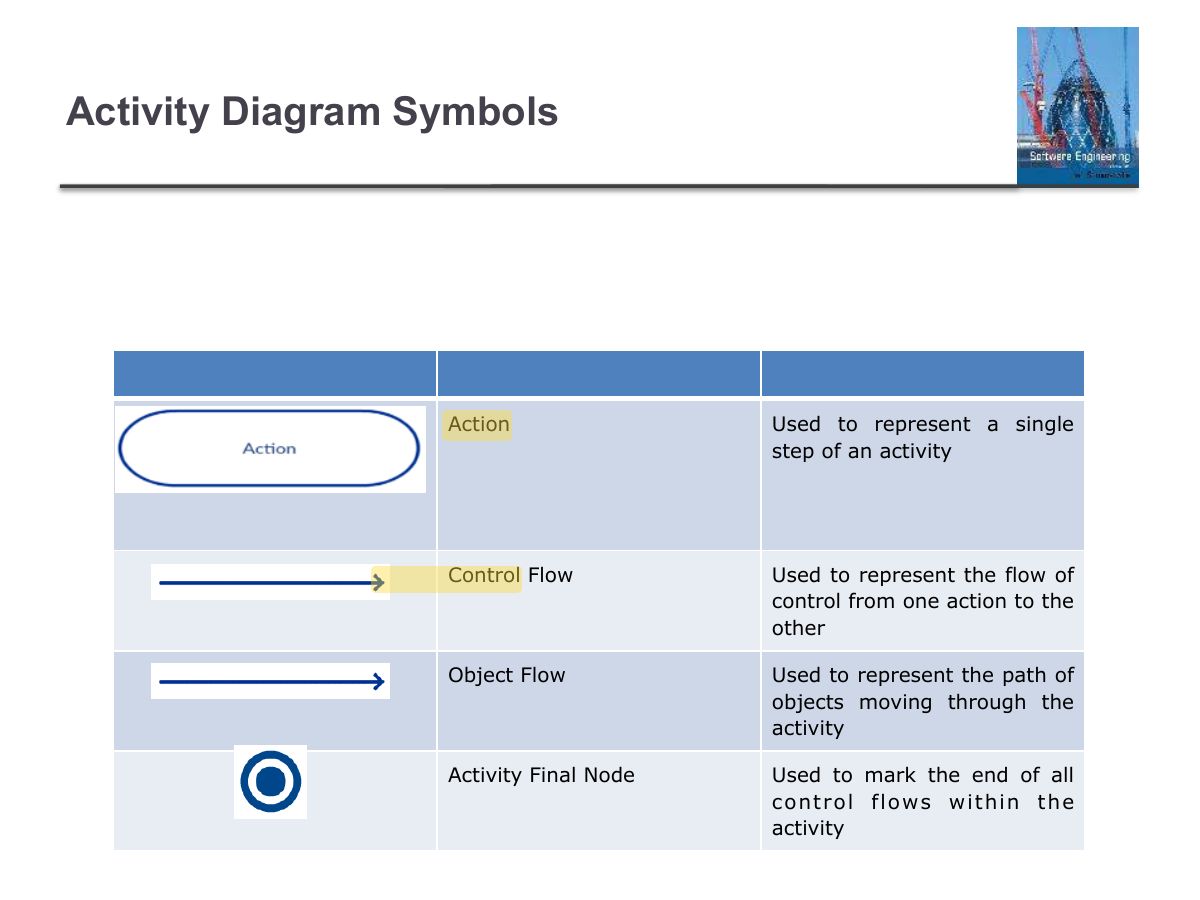
                                                                                                                                                        Slide 91: Activity Diagram Symbols
                                                                                                                                                        Exam weight Low
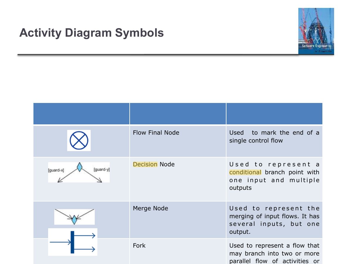
                                                                                                                                                          Slide 92: Activity Diagram Symbols
                                                                                                                                                          Exam weight Low
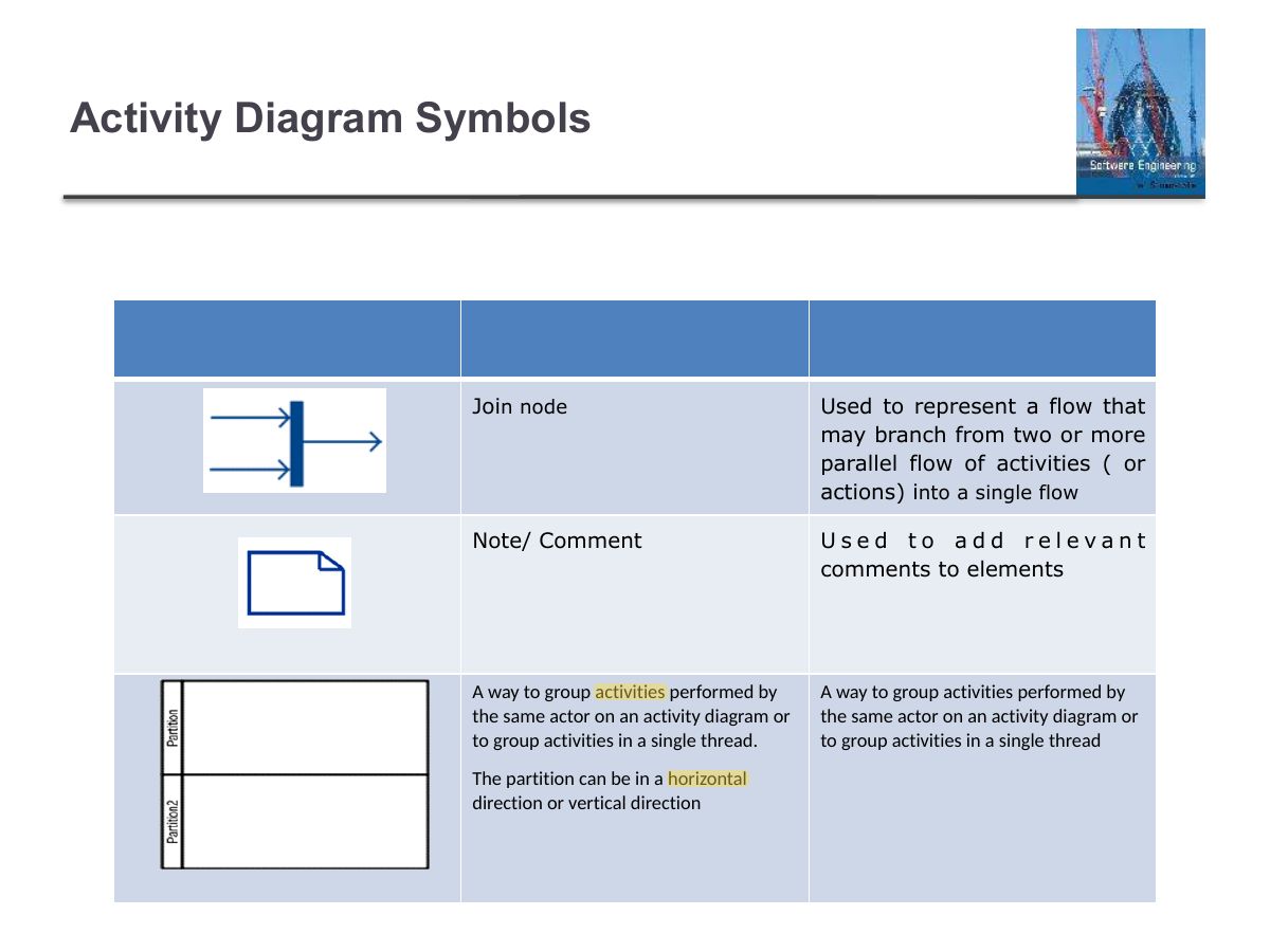
                                                                                                                                                            Slide 93: Activity Diagram Symbols
                                                                                                                                                            Exam weight Low
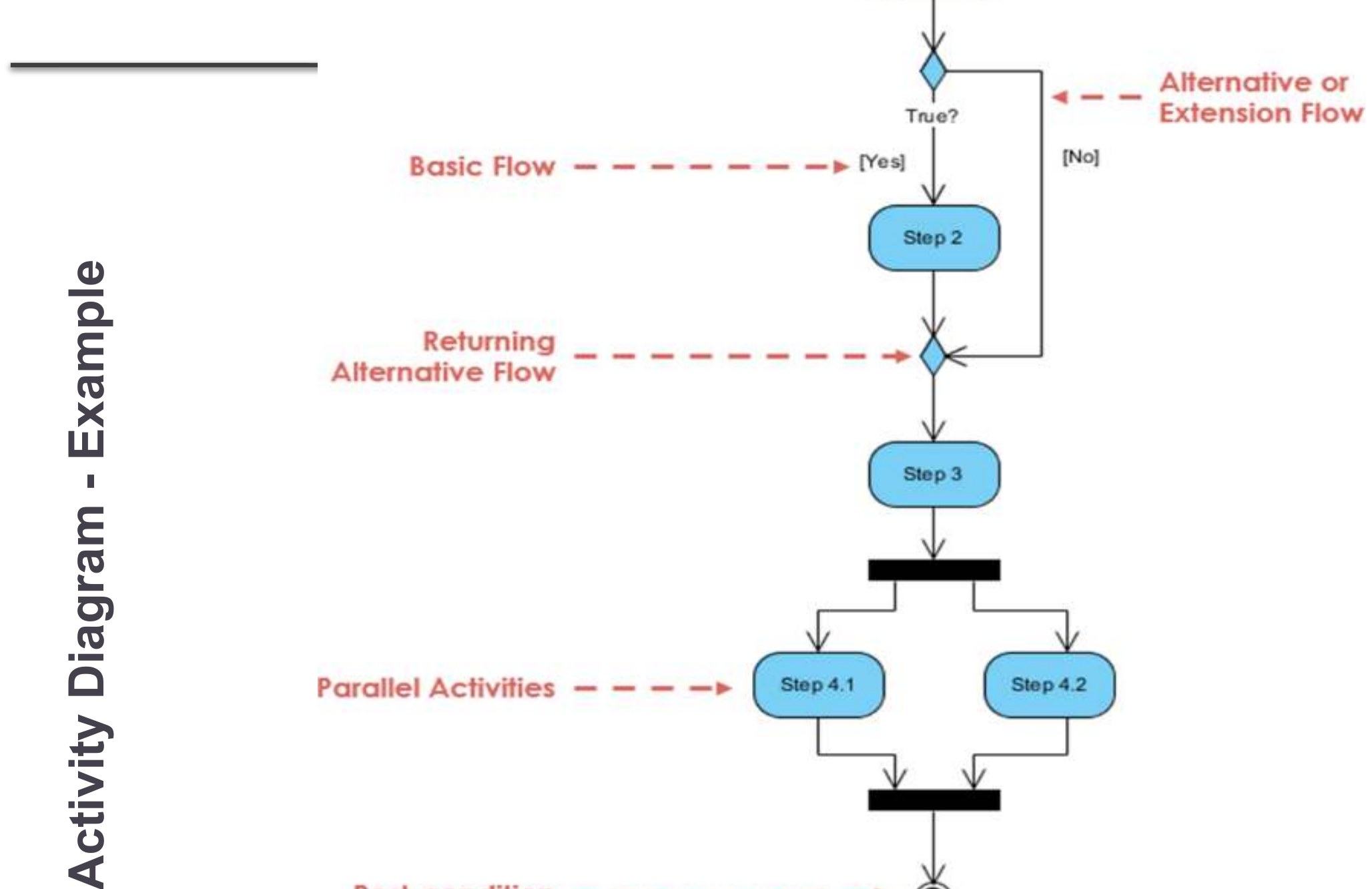
                                                                                                                                                              Slide 94: Activity Diagram Symbols
                                                                                                                                                              Exam weight Low

                                                                                                                                                                e l p m ax E

                                                                                                                                                                • m a r g a i

                                                                                                                                                                D y t i v i t c A

                                                                                                                                                                Slide 95
                                                                                                                                                                95
                                                                                                                                                                Exam weight Low

                                                                                                                                                                  Activity Diagram - Process Order

                                                                                                                                                                  ◇

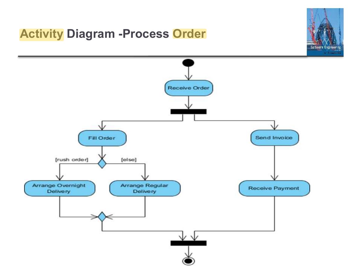
                                                                                                                                                                  In the following slide we have an activity diagram that describes the workflow for processing an order:

                                                                                                                                                                  ◇

                                                                                                                                                                  Once the order is received, the activities split into two parallel sets of activities. One side fills and sends the order while the other handles the billing.

                                                                                                                                                                  ◇

                                                                                                                                                                  On the Fill Order side, the method of delivery is decided conditionally. Depending on the condition either the Overnight Delivery activity or the Regular Delivery activity is performed.

                                                                                                                                                                  ◇

                                                                                                                                                                  Finally, the parallel activities combine to close the order.

                                                                                                                                                                  Activity Diagram - Process Order
                                                                                                                                                                  96
                                                                                                                                                                  Exam weight Low
                                                                                                                                                                    Slide 97: Activity Diagram -Process Order
                                                                                                                                                                    Exam weight Low

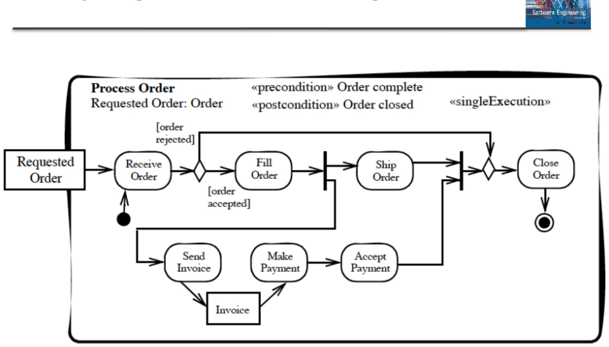
                                                                                                                                                                      Activity Diagram for Order Handling

                                                                                                                                                                      Activity Diagram for Order Handling
                                                                                                                                                                      98
                                                                                                                                                                      Exam weight Low

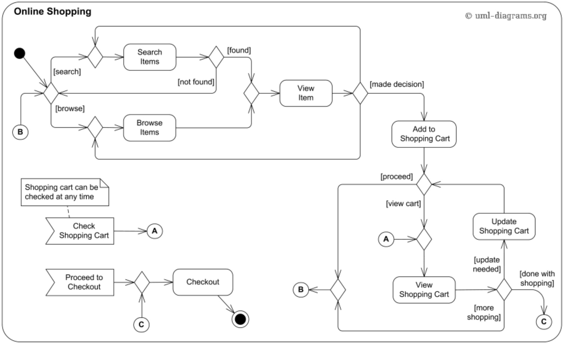
                                                                                                                                                                        Activity diagram of : online shopping

                                                                                                                                                                        30/10/2014

                                                                                                                                                                        Chapter 5 System Modeling

                                                                                                                                                                        Activity diagram of : online shopping
                                                                                                                                                                        99
                                                                                                                                                                        Exam weight Low
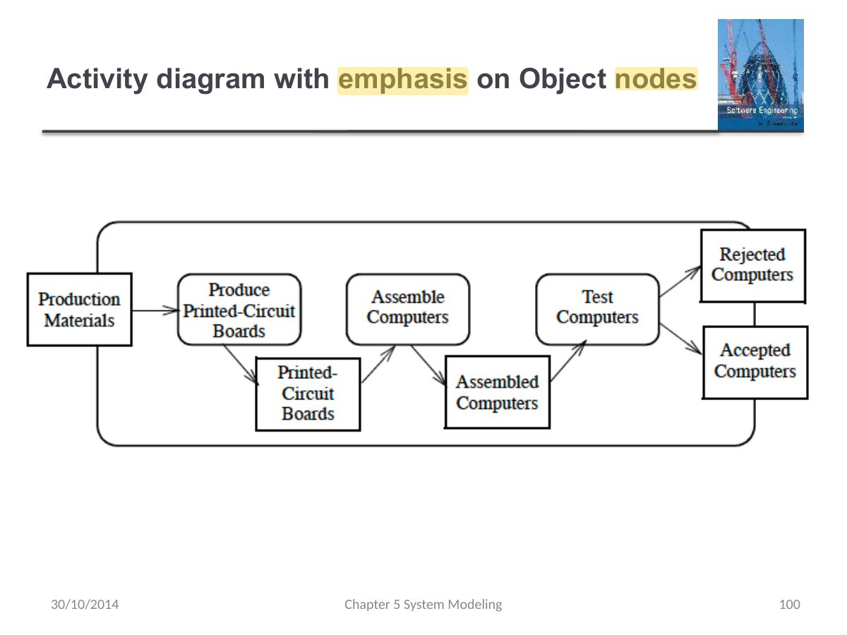
                                                                                                                                                                          Slide 100: Activity diagram with emphasis on Object nodes
                                                                                                                                                                          Exam weight Low
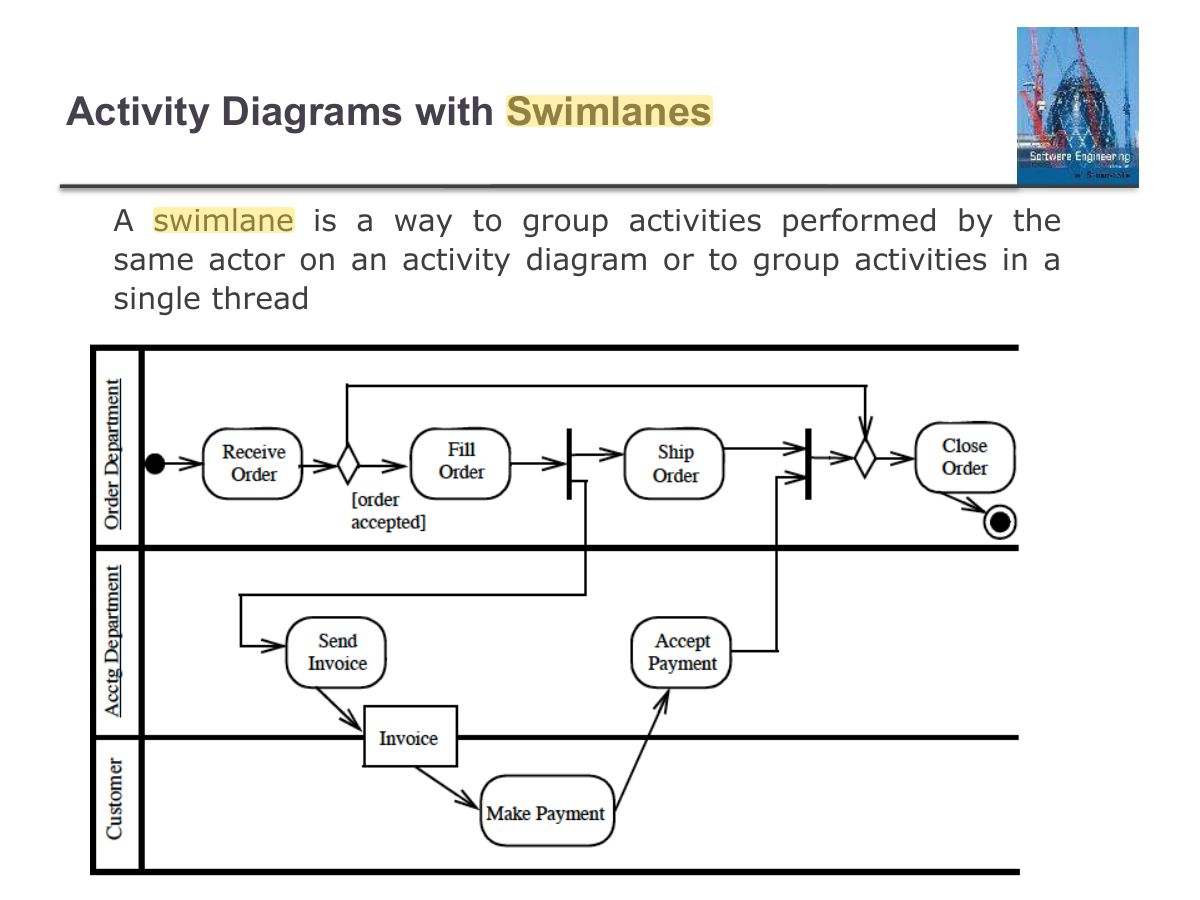
                                                                                                                                                                            Slide 101: Activity Diagrams with Swimlanes
                                                                                                                                                                            Exam weight Low
                                                                                                                                                                            1. Swimlanes show WHO performs each activity.

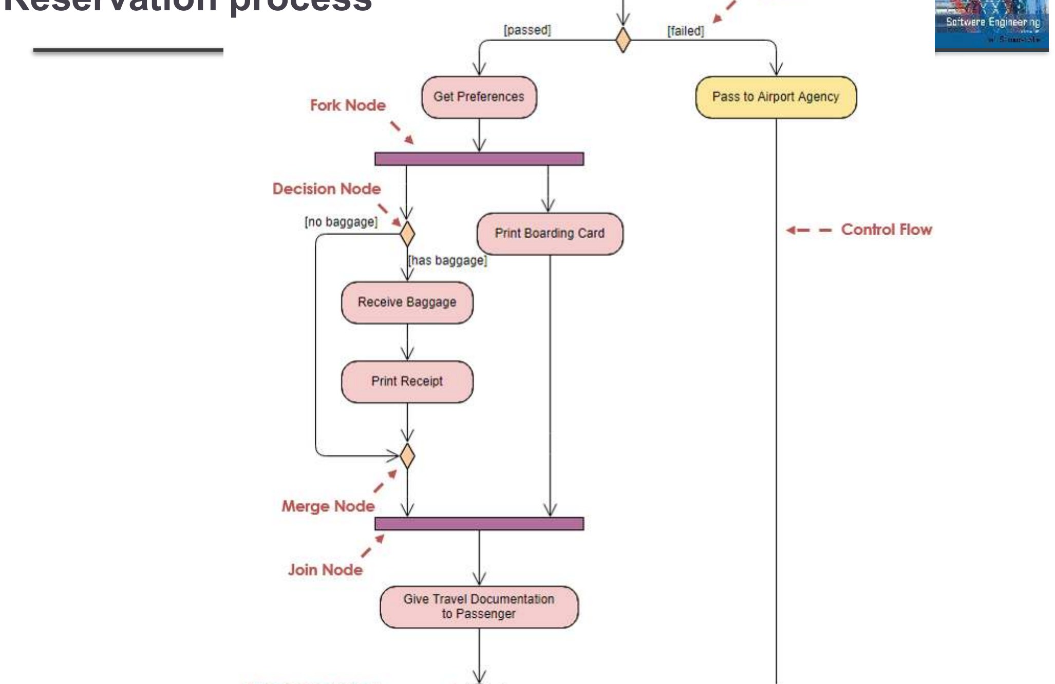
                                                                                                                                                                            Activity Diagram Reservation process

                                                                                                                                                                            Activity Diagram Reservation process
                                                                                                                                                                            102
                                                                                                                                                                            Exam weight Low

                                                                                                                                                                              Statechart (or state Machine) Diagram

                                                                                                                                                                              ◇

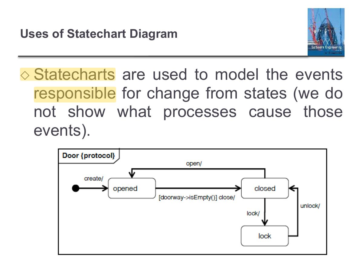
                                                                                                                                                                              It’s a behavioral diagram. State diagrams are also referred to as State machines and Statechart Diagrams.
                                                                                                                                                                              ◇

                                                                                                                                                                              The State machine diagram can be used for modeling discrete behaviour through finite state transition systems.
                                                                                                                                                                              ◇

                                                                                                                                                                              A state diagram is used to model the dynamic behavior of a class in response to time and external stimuli.

                                                                                                                                                                              Statechart (or state Machine) Diagram
                                                                                                                                                                              103
                                                                                                                                                                              Exam weight High
                                                                                                                                                                              1. State machine: states an object can be in and the transitions triggered by events [guard] / action.
                                                                                                                                                                              🎯 How this can come up · 1 question
                                                                                                                                                                              MCQ

                                                                                                                                                                              Which diagram best shows how one object changes state in response to events?

                                                                                                                                                                              Slide 104: Uses of Statechart Diagram
                                                                                                                                                                              Exam weight Low
                                                                                                                                                                                Slide 105: Basic Components of a State Chart Diagram
                                                                                                                                                                                Exam weight Low

                                                                                                                                                                                  Basic Components of a State Chart Diagram

                                                                                                                                                                                  ◇

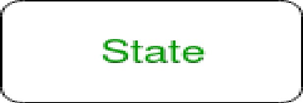
                                                                                                                                                                                  State – We use a rounded rectangle to represent a state.

                                                                                                                                                                                  A state represents the conditions or circumstances of an object of a class at an instant of time.

                                                                                                                                                                                  Figure – state notation

                                                                                                                                                                                  Basic Components of a State Chart Diagram
                                                                                                                                                                                  106
                                                                                                                                                                                  Exam weight Low
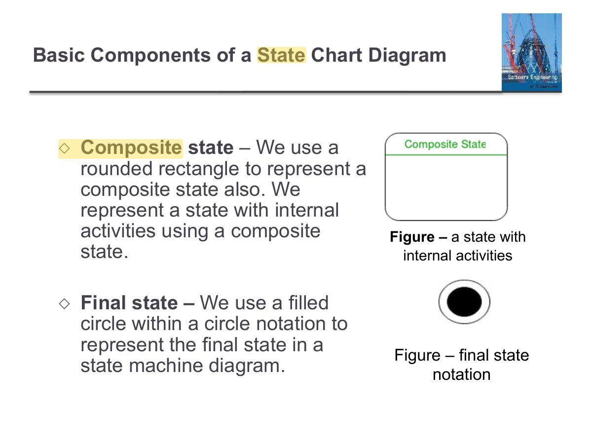
                                                                                                                                                                                    Slide 107: Basic Components of a State Chart Diagram
                                                                                                                                                                                    Exam weight Low
                                                                                                                                                                                      Slide 108: Basic Components of a State Chart Diagram
                                                                                                                                                                                      Exam weight Low
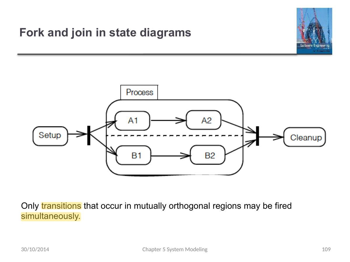
                                                                                                                                                                                        Slide 109: Fork and join in state diagrams
                                                                                                                                                                                        Exam weight Low

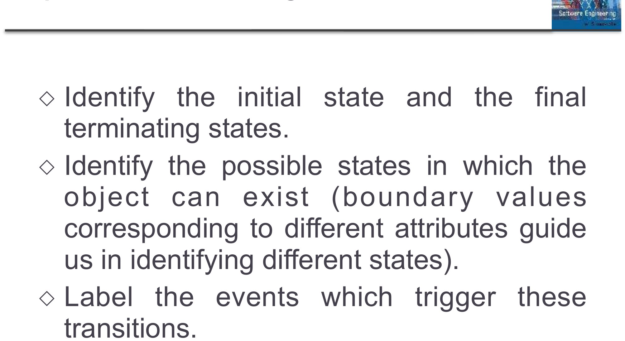
                                                                                                                                                                                          Steps to Draw a State Diagram

                                                                                                                                                                                          ◇

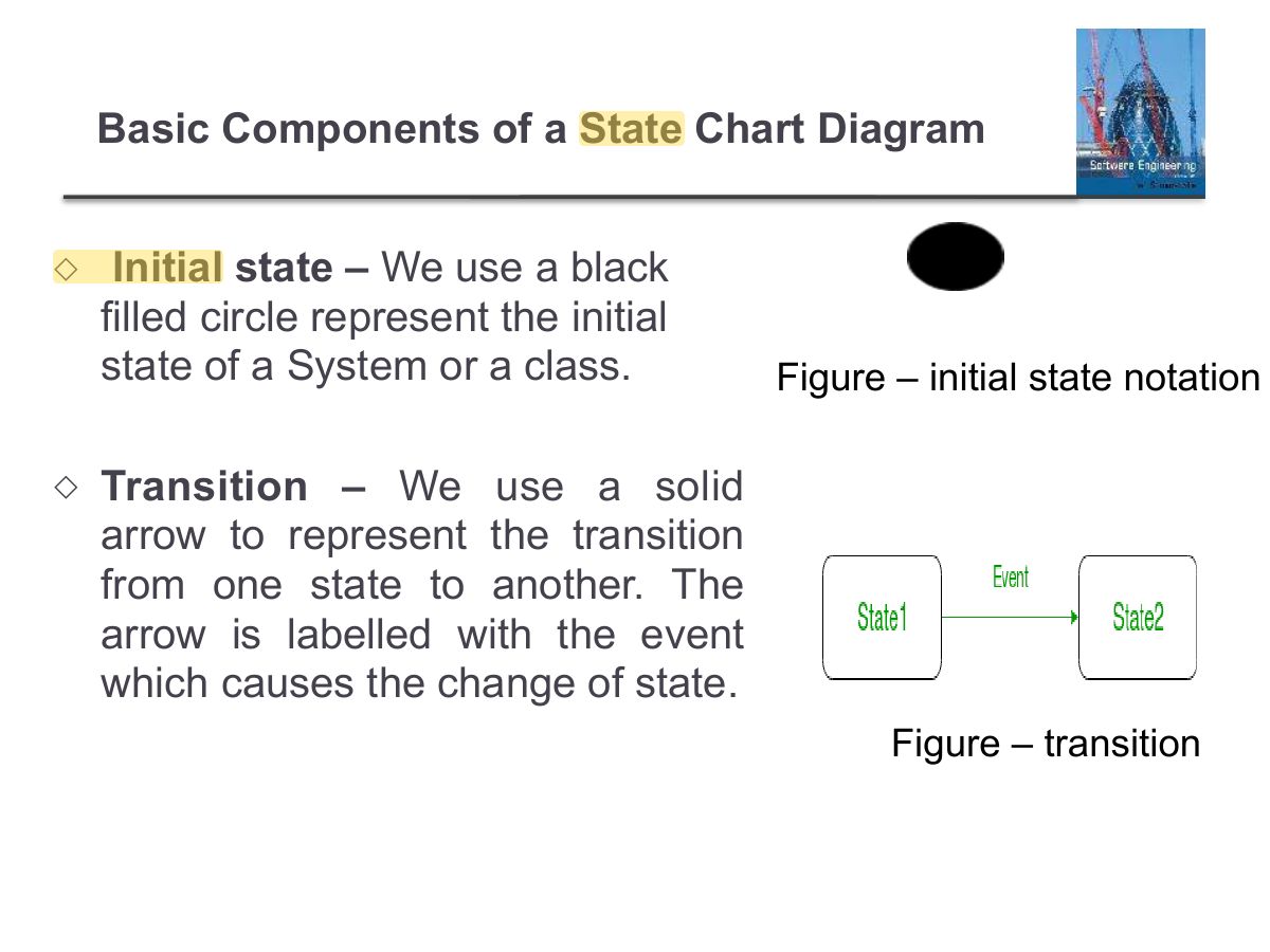
                                                                                                                                                                                          Identify the initial state and the final terminating states.

                                                                                                                                                                                          ◇

                                                                                                                                                                                          Identify the possible states in which the

                                                                                                                                                                                          • b j e c t c a n e x i s t (b o u n d a r y v a l u e s corresponding to different attributes guide us in identifying different states).

                                                                                                                                                                                          ◇

                                                                                                                                                                                          Label the events which trigger these transitions.

                                                                                                                                                                                          Steps to Draw a State Diagram
                                                                                                                                                                                          110
                                                                                                                                                                                          Exam weight Low

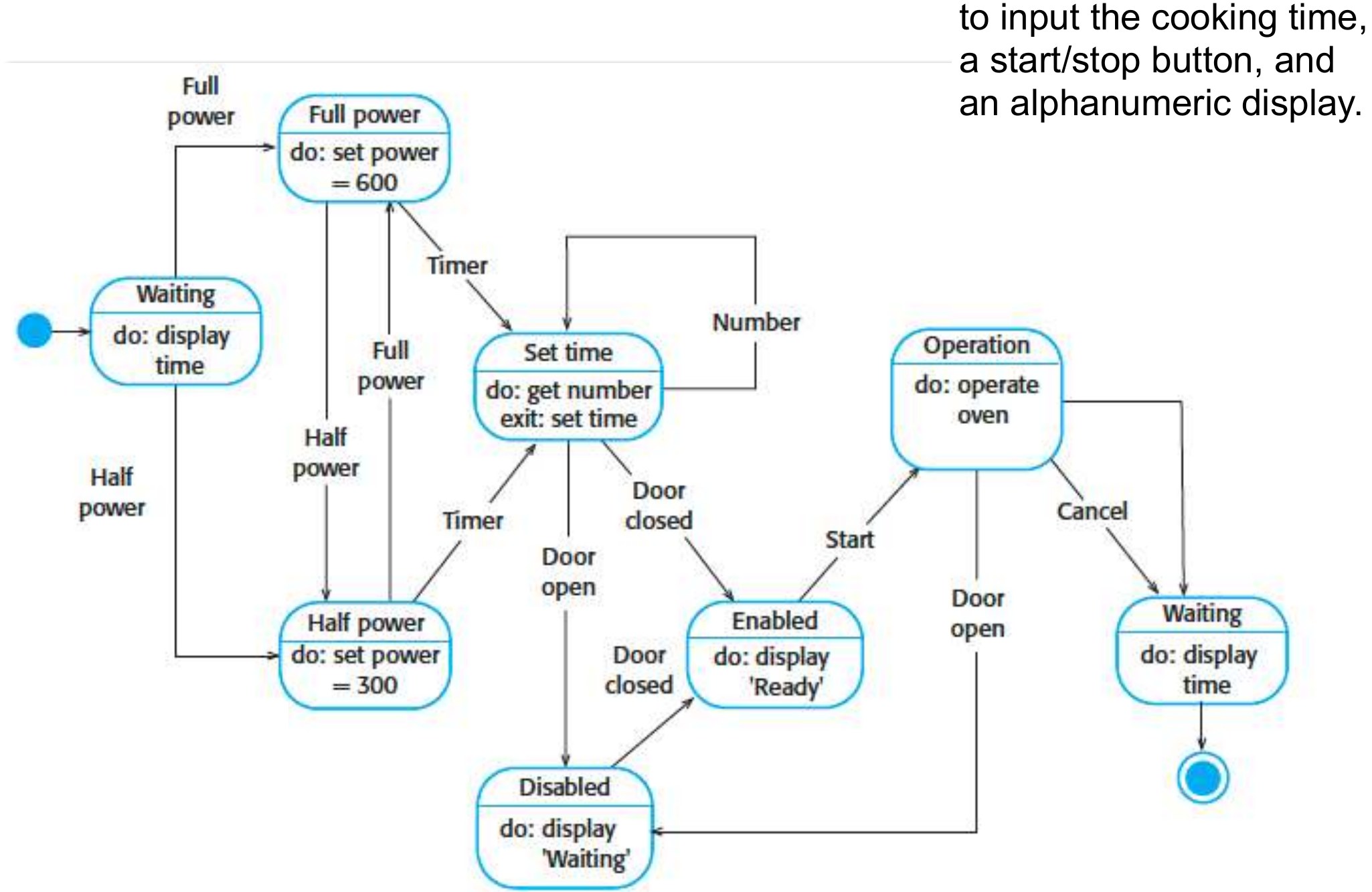
                                                                                                                                                                                            This simple oven has a switch to select full or half

                                                                                                                                                                                            State diagram of a microwave oven

                                                                                                                                                                                            power, a numeric keypad to input the cooking time, an alphanumeric display.

                                                                                                                                                                                            This simple oven has a switch to select full or half
                                                                                                                                                                                            111
                                                                                                                                                                                            Exam weight Low

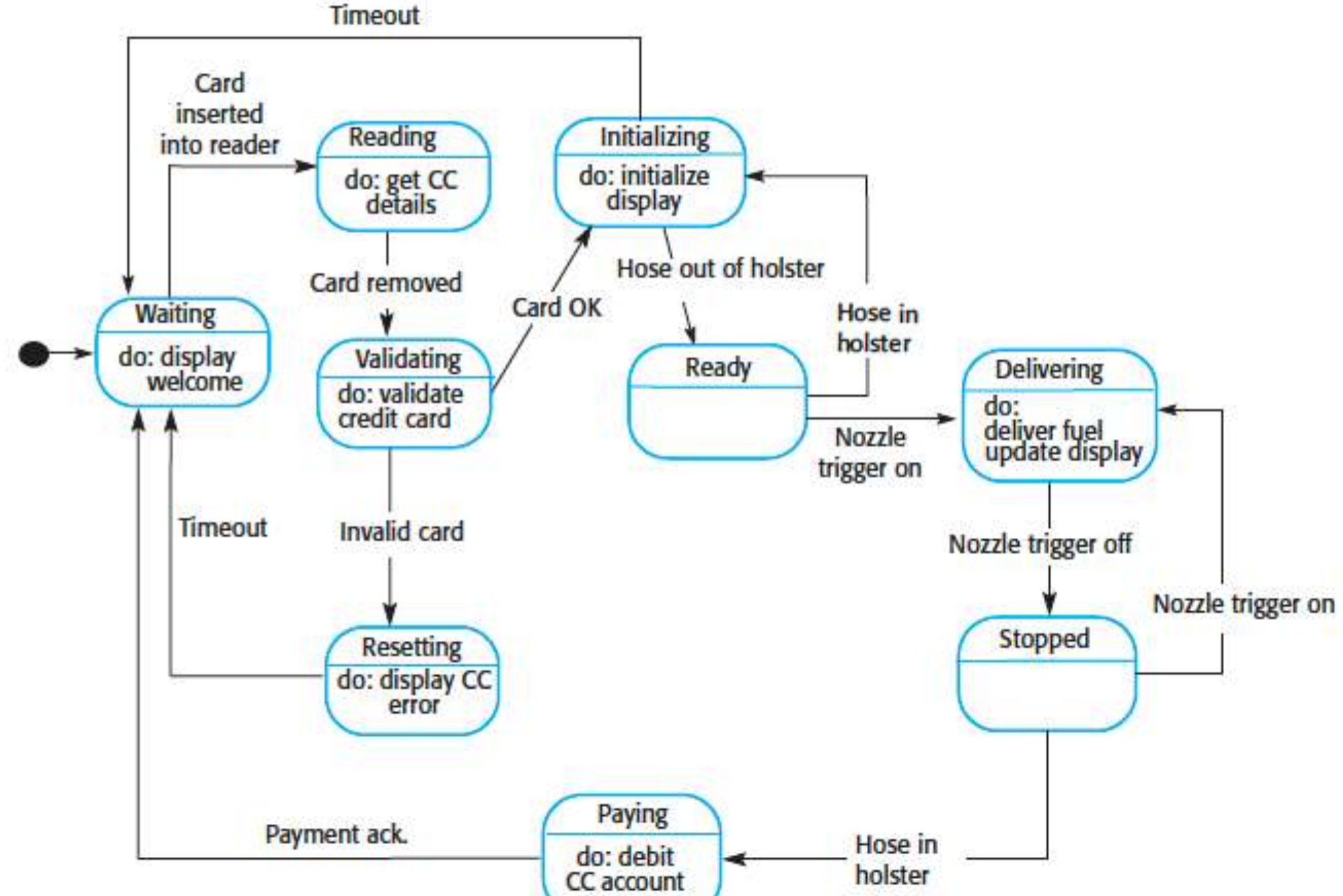
                                                                                                                                                                                              State diagram example: Petrol pump

                                                                                                                                                                                              State diagram example: Petrol pump
                                                                                                                                                                                              112
                                                                                                                                                                                              Exam weight Low