🎯 Complete UML & Software Engineering Diagrams Guide
Use Case Diagram
Behavioral • Requirements📍 When to Use:
Use when you need to show WHO (actors) can do WHAT (use cases) with the system. Perfect for capturing functional requirements and system boundaries.

Example Use Case diagram (ATM system) from the course slides.
Relationships:
Real Exam Example - ATM System
Solution Approach:
- Actors: Customer, Maintenance Person, Bank System
- Main Use Cases: Withdraw Cash, Deposit Funds, Transfer Funds
- Include: Validate User (included by all transactions)
- Extend: Handle Insufficient Funds, Exceeds Daily Limit (extend Withdraw Cash)
- Additional: Refill ATM (by Maintenance Person)
💡 Exam Tips & Tricks:
- Always identify ALL actors first - look for roles, not specific people
- Use INCLUDE when something MUST happen (validation, authentication)
- Use EXTEND for optional/conditional scenarios (error handling, special cases)
- System boundary contains use cases ONLY, actors stay outside
- Name use cases as verb + noun (e.g., "Withdraw Cash", "Validate User")
Class Diagram
Structural • Static📍 When to Use:
Use to show the STRUCTURE of the system - classes, their attributes, methods, and relationships. Essential for object-oriented design.
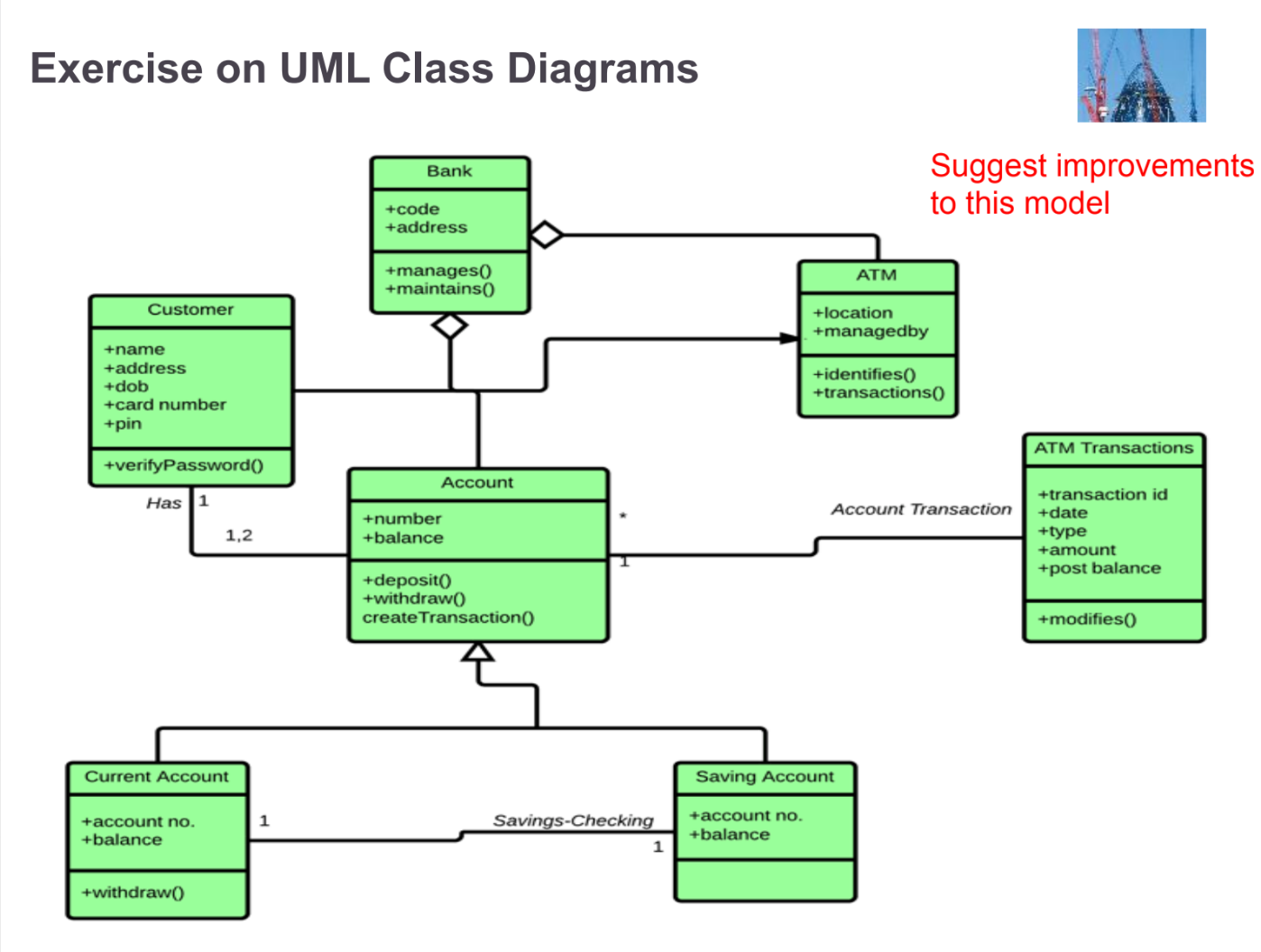
Example UML Class diagram (Bank / ATM / Account) from the course slides.
+ public
- private
# protected
~ package
Relationships:
Real Exam Example - Company Employee System
Solution Approach:
- Classes: Company, Employee, Manager, Contractor
- Inheritance: Manager and Contractor inherit from Employee
- Aggregation: Company has Employees (1..*)
- Association: Manager supervises Employees (1..*)
- Attributes: Company (name, address), Employee (empNumber, name, salary), Contractor (+contractLength)
💡 Exam Tips & Tricks:
- Always check multiplicity: 1 (exactly one), 0..1 (optional), * (many), 1..* (at least one)
- Aggregation (◇) = "uses a" - Team HAS Players (players can exist without team)
- Composition (◆) = "is part of" - House HAS Rooms (rooms can't exist without house)
- Look for IS-A relationships for inheritance (Manager IS-A Employee)
- Derived attributes start with "/" (e.g., /age calculated from birthDate)
Sequence Diagram
Behavioral • Dynamic📍 When to Use:
Use to show HOW objects interact over TIME. Perfect for modeling the flow of messages in a specific scenario.
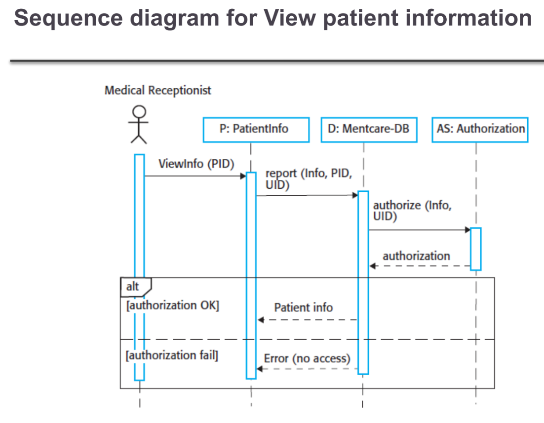
Example Sequence diagram (View patient information) from the course slides.
Real Exam Example - Database Transaction
Key Elements to Identify:
- c:Client is the notation for an object named 'c' of class 'Client'
- The vertical dotted line is the lifeline
- The narrow rectangle on lifeline is activation (when object is processing)
- setValues(d,3,4) is a method call with parameters
- ODBCProxy is the suitable class for database operations
💡 Exam Tips & Tricks:
- Time flows from TOP to BOTTOM - earlier messages are higher
- Alt frame = if-then-else, Loop frame = repetition, Opt frame = optional
- Self-message: arrow that loops back to same object
- Object creation: message pointing to object box (not lifeline)
- Object destruction: X at end of lifeline
Activity Diagram
Behavioral • Flow📍 When to Use:
Use to show WORKFLOW or PROCESS FLOW. Like an advanced flowchart with parallel activities and swimlanes.
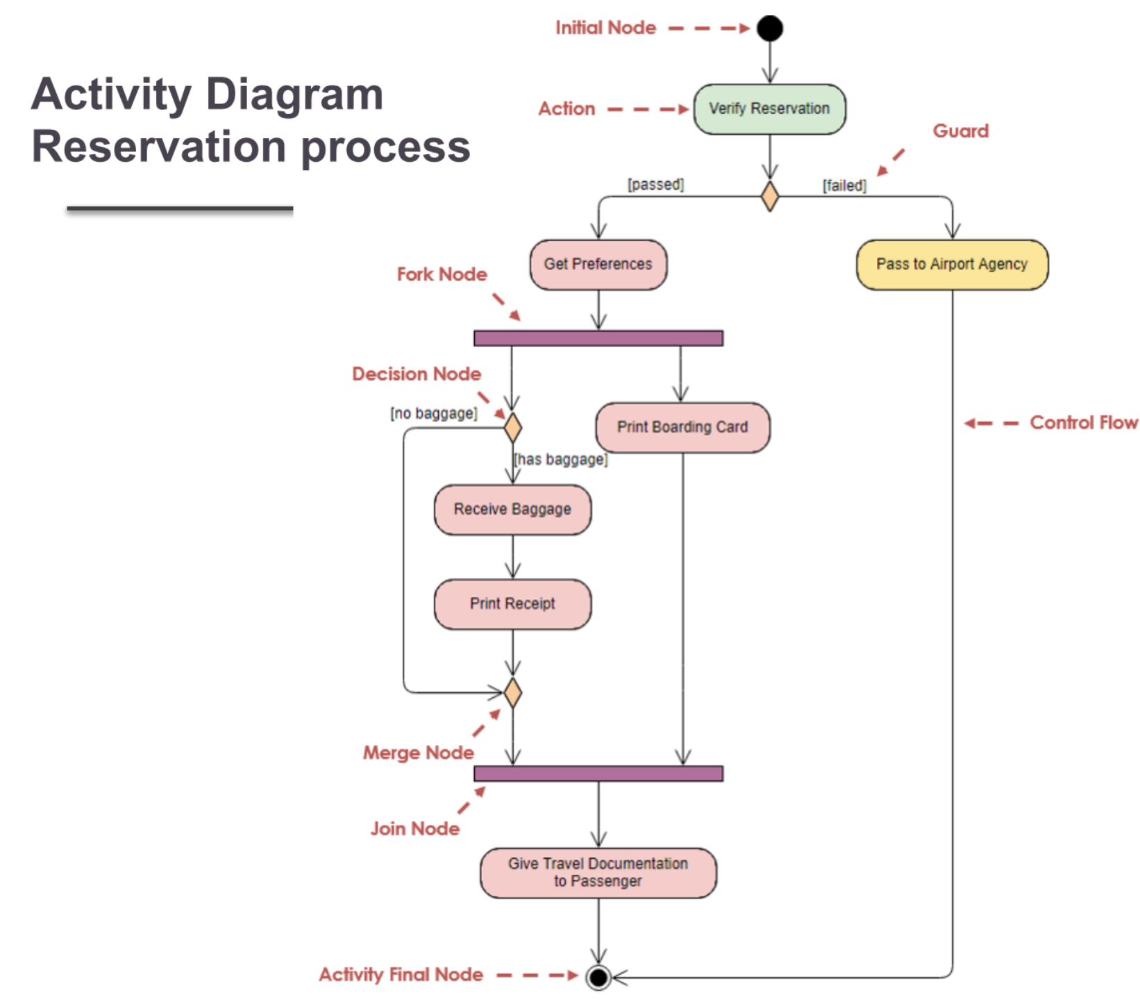
Example Activity diagram (Reservation process) from the course slides.
Real Exam Example - Flight Check-in Process
Solution with Swimlanes:
- Swimlane 1: Passenger - Show Ticket, Check Luggage, Pay Fees
- Swimlane 2: Passenger Services - Verify Ticket, Accept Luggage, Check Fees, Issue Boarding Pass
- Swimlane 3: Customer Service - Handle Invalid Tickets
- Decision Points: [Ticket OK?], [Fees Required?]
- Flow: Sequential with conditional branches
💡 Exam Tips & Tricks:
- Fork (─) splits into parallel activities, Join (─) merges them back
- Decision (◇) has ONE input, MULTIPLE outputs with guards [condition]
- Merge (◇) has MULTIPLE inputs, ONE output (no conditions)
- Swimlanes group activities by actor/department - use when multiple actors involved
- Object nodes [rectangles] show data flowing between activities
State Machine/Statechart Diagram
Behavioral • State Transitions📍 When to Use:
Use to show how an object changes STATES in response to EVENTS. Perfect for modeling lifecycle of objects.
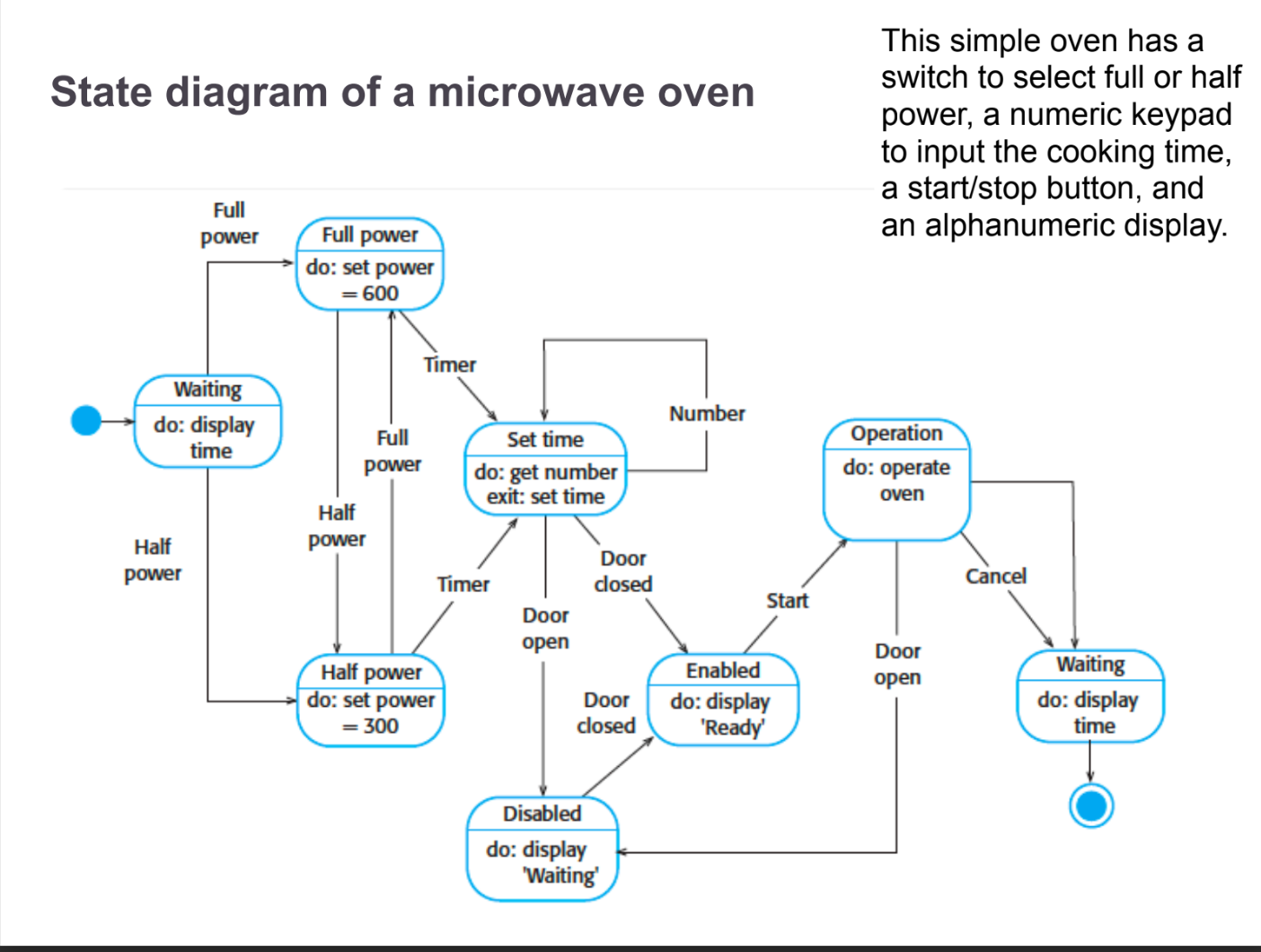
Example State diagram from the course slides.
Real Exam Example - Microwave Oven
States & Transitions:
- States: Idle, Set Power, Set Time, Cooking, Paused, Complete
- Initial State → Idle: System starts
- Idle → Set Power: Power button pressed
- Set Power → Set Time: Time button pressed
- Set Time → Cooking: Start button pressed
- Cooking → Paused: Stop button pressed
- Cooking → Complete: Timer expires
💡 Exam Tips & Tricks:
- Self-transition: arrow loops back to same state (state doesn't change)
- Guard conditions in square brackets: [balance > 0]
- Actions after slash: buttonPressed/lightOn
- Entry/Exit actions: performed when entering/leaving state
- Fork (─) and Join (─) for concurrent states
Exam Strategy: Choosing the Right Diagram
📝 Read the Scenario Keywords:
- "actors", "users", "system functions" → Use Case Diagram
- "classes", "attributes", "inheritance", "has-a" → Class Diagram
- "message flow", "interaction", "time sequence" → Sequence Diagram
- "workflow", "process", "parallel activities" → Activity Diagram
- "states", "transitions", "events", "lifecycle" → State Diagram
🏆 Universal Exam Tips:
- Always draw a rough sketch first before the final diagram
- Label EVERYTHING - no unlabeled arrows or relationships
- Show multiplicity in class and use case diagrams (1, *, 0..1, 1..*)
- Use proper UML notation - don't invent your own symbols
- Include a legend if using any non-standard notation
- For scenarios, identify actors/objects FIRST, then actions/relationships
- When in doubt, add a note to explain your reasoning